An Electric Drive Eclipse (ED-E) Version 2.1b
| PRELIMINARY VERSION PRELIMINARY VERSION PRELIMINARY VERSION PRELIMINARY VERSION | ||||
|
An Electric Drive Eclipse (ED-E) Version 2.1b |
||||
|
|
|||
|
|
|||
| Introduction |
|
The conversion of a stock petrol fueled automobile into an electric vehicle is a relatively straight forward process. One removes all the internal combustion engine (ICE) related items, including the engine, exhaust piping, catalytic converter, muffler, fuel tank, fuel pump, etc. Next, one installs a big electric motor, a large number of batteries, a DC controller, and a few other required items... and you have an electric vehicle. A quality conversion will take 9 to 18 months, and will often - in reality - cost as much as $10,000 to $15,000. This price is assuming the traction battery pack is provided by valve-regulate lead acid (VRLA) batteries, and does not include the cost of the donor vehicle. A typical driving range of 25 to 40 miles can be expected, if a very light weight donor vehicle is used, and the traction pack employed is at least 120 to 150 volts (nominal). If a heavy donor vehicle is employed, such as is the case with my Eclipse, then the range with VRLA batteries is typically 10 to 25 miles, depending on the type of driver, driving terrain, and the ambient temperature. A range of something like 30 to 60 miles can be expected if Lithium batteries are used to replace the current Eclipse VRLA batteries. As one looks around the Internet, it is clear that the overall quality and operational aspects of conversions can vary widely. The selected major components, along with a variety of custom manufactured pieces, must be adapted and coupled to the donor vehicle with care and cunning.
|
| Project Overview |
|
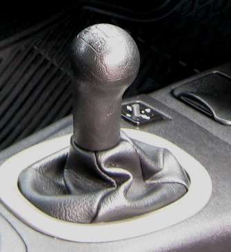
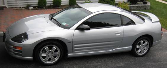
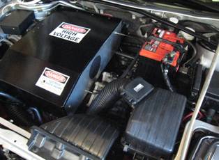
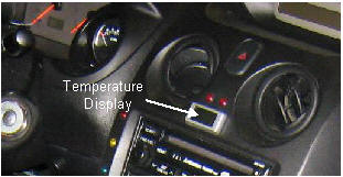
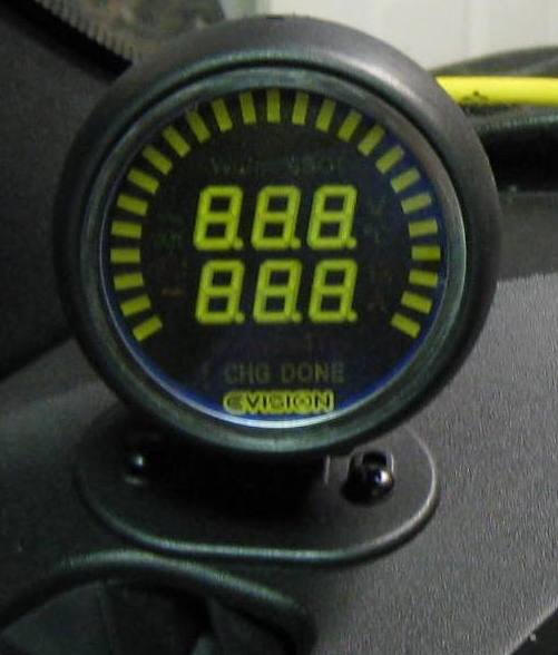
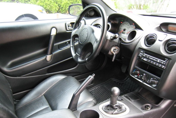
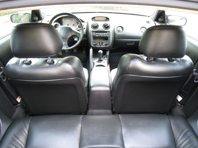
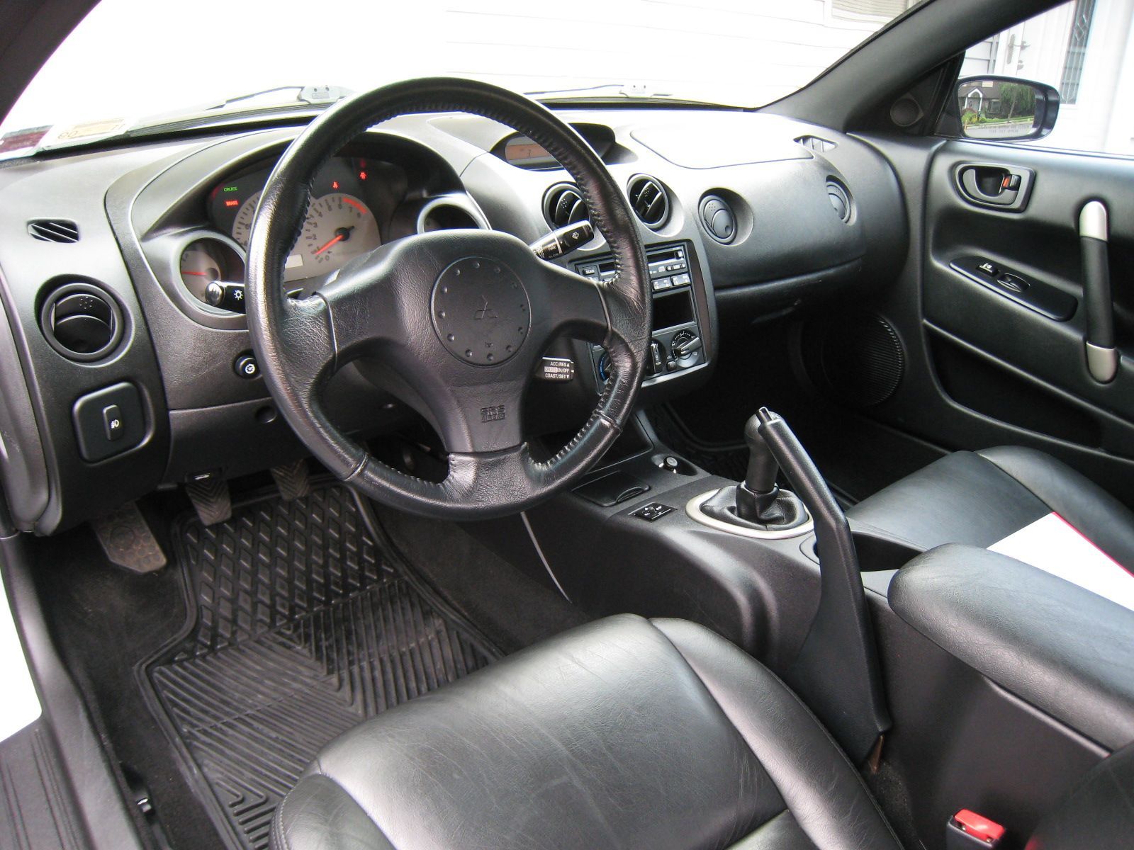
The Electric-Drive Eclipse (ED-E) project, which is concisely documented in this very long webpage, resulted in the conversion of a 2002 Mitsubishi Eclipse from a gas powered vehicle to a two-passenger battery electric vehicle (BEV), which has power steering and A/C, and is quite highway capable. A goal of this conversion was to produce a reliable and very stock looking vehicle. There are only a few very subtle indications that this car is not stock. First, there is no exhaust pipe. Second, the interior instrumentation has been altered to include a number of helpful electric vehicle instruments and readouts. For example, a Metric Mind Corporation... EVision System has been added with the Triple Display Module mounted by the driver's side A-pillar. An additional module of the EVision System - termed a Human Interface Module - is mounted in the center console, just behind the fully functional manual 5-speed shift lever. In addition, a six-sensor temperature monitoring system has been included for monitoring the temperature of the motor, controller, DC-DC converter, the mid-car battery box, the rear-car battery box, and the outside/ambient temperature. Otherwise the car looks completely stock - until you open the hood! Another major goal of this conversion was to produce a fully functional electric vehicle that could be used for around town driving, and for work and back. Not only does my place of employment have a number of charging stations, at the present moment there is NO charge for using them! Currently, ED-E uses about 1/2 the pack power to get the ~10 miles to work - with the current AGM lead acid traction pack. This current traction pack weighs in at 1050 pounds!! The presently planned lithium traction pack, which will fill a bit less volume, will reduce the battery traction pack weight by over 600 pounds. And this planned lithium pack should have about two to three times the useful power of the current pack. |
| ---------------------------------------------------------------------------------------------------------------------------------------------------- |
|
|
| The conversion of the Eclipse to electric-drive includes the use of a set of high quality industry standard components. The selected components are reliable and specifically designed for use in electric vehicles and conversion vehicles. A short list of the major components is provided below: |
| ----------------------------------------------------------------------------------------------------------------------------------------------- | |||
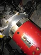
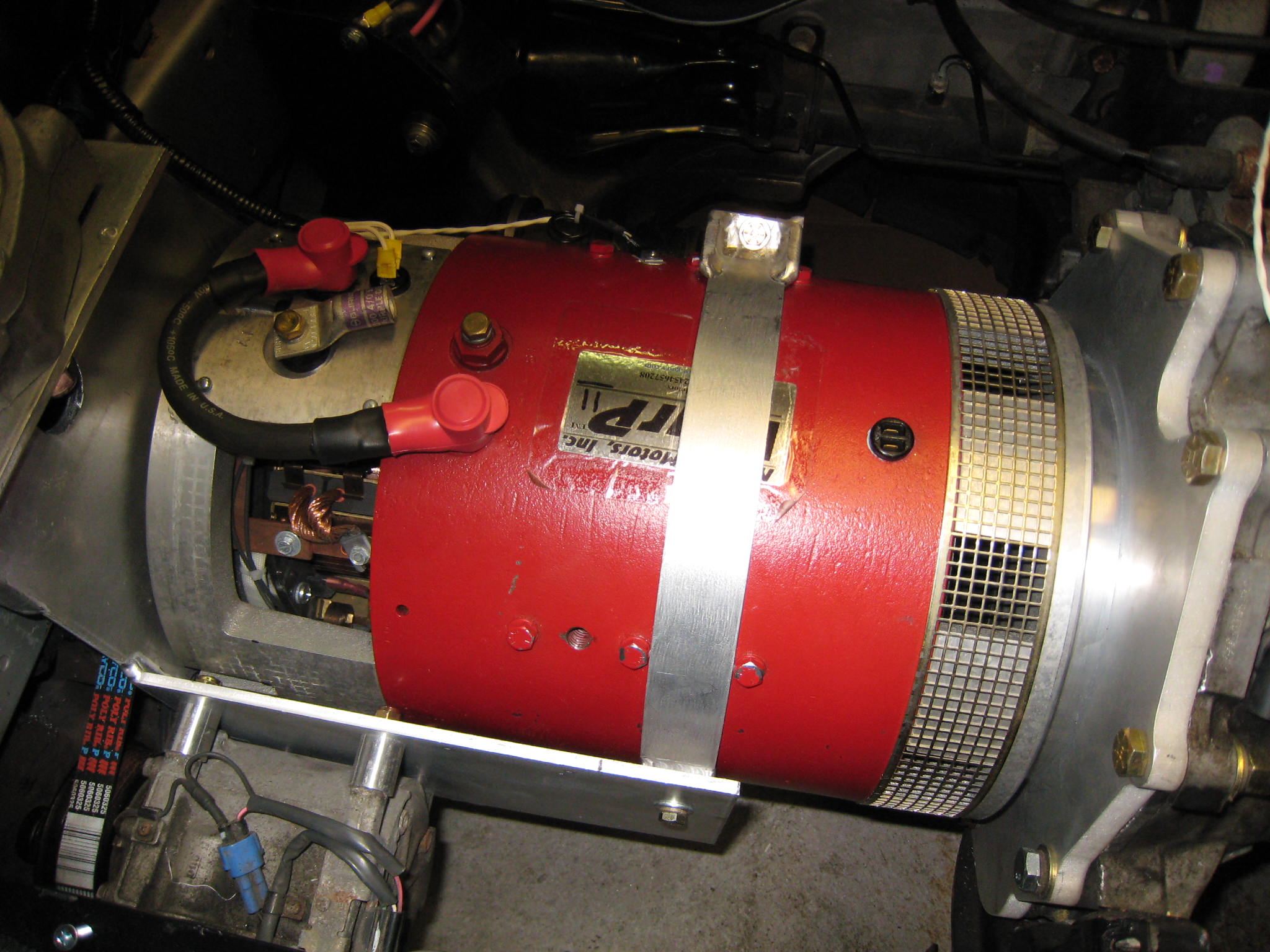
| Motor: |
|
NetGain WarP11 Series Wound DC Motor: - 11" Diameter; - 1/2" Aluminum Adapter Plate; - 4" filtered air intake; - Inline 12V temp-activated; tube blower. |
|
| ----------------------------------------------------------------------------------------------------------------------------------------------- | |||
| Transmission: |
|
Original Factory short throw 5-Speed, with fully functional clutch |
| ----------------------------------------------------------------------------------------------------------------------------------------------- | ||
| Controller: |
|
Raptor 1200, PWM High Voltage DC Controller (Rated for 190V @ 1200A max, burst) |
| ----------------------------------------------------------------------------------------------------------------------------------------------- | |
|
Traction Pack: |
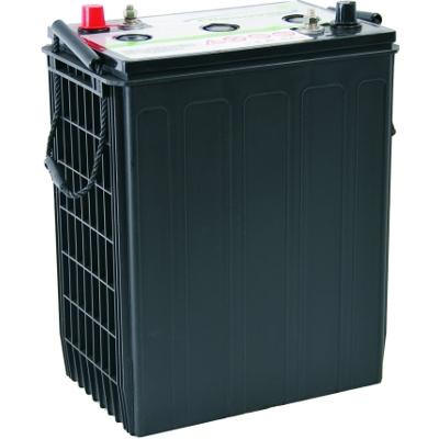 |
| Sixteen 8V
EVGC8A Discover AGM
Valve Regulated Lead Acid
Batteries (128 VDC nominal, ~22 kWh on-paper) |
|
| ----------------------------------------------------------------------------------------------------------------------------------------------- | ||
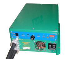
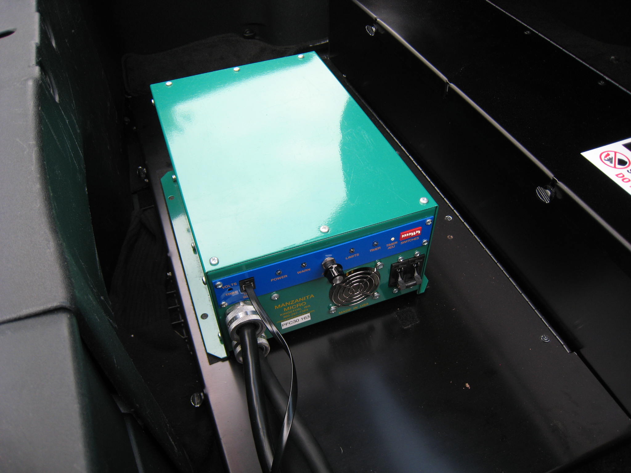
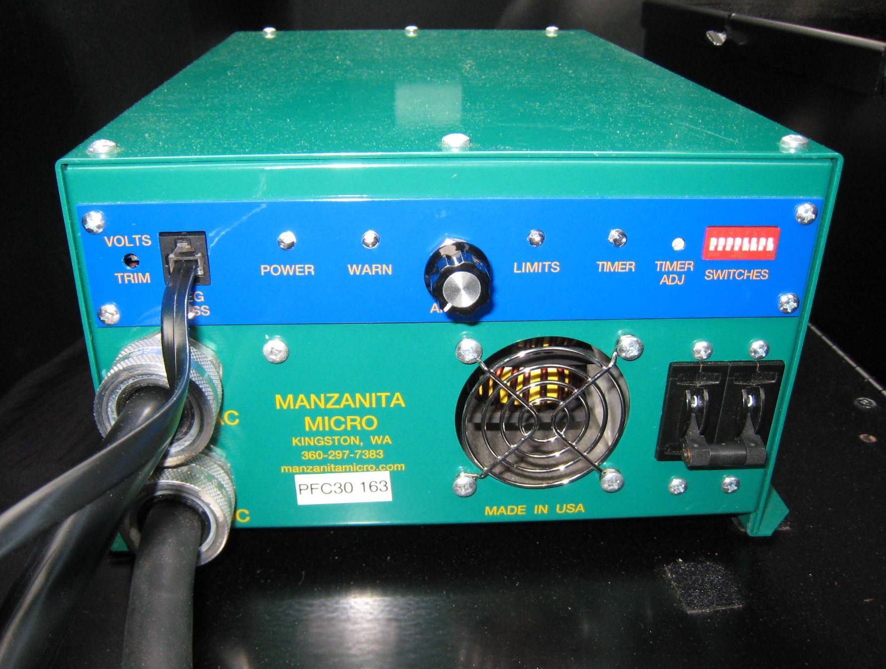
| On-Board Charger: |
|
Manzanita Micro PFC-30 Series Charger: Input Voltage : 100 - 240 VAC ; Output Voltage : 12 to 450 VDC Current Traction Pack Limit Voltage: 151 VDC |
| ----------------------------------------------------------------------------------------------------------------------------------------------- | ||
| Battery Management System (BMS) |
|
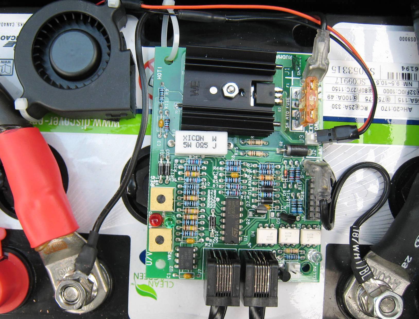
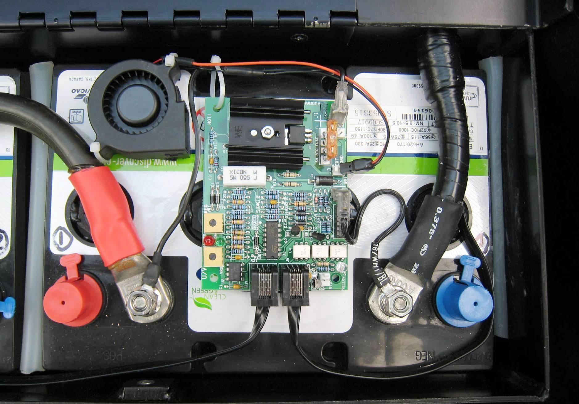
16 Manzanita Rudman Regulator Modules:
MK2d Analog shunting regulator Each regulator is velcro mounted to the top of a battery Each reg includes a shunt activated blower REG-BUS interfaced to PFC-30 charger |
| ----------------------------------------------------------------------------------------------------------------------------------------------- | ||
|
Passenger Compartment |
 |
Ceramic 1500W Heater
(Installed in-dash, within original heater-core) |
| ----------------------------------------------------------------------------------------------------------------------------------------------- | ||
|
Instruments: |
 |
| In-Dash:
Voltmeter, Ammeter, Speedometer, Tachometer (All functioning); Added: 6-station temperature monitoring system, TMS (motor, controller, DC-DC unit, batt-box1, batt-box2, ambient) EVision M2 System (with the HMI center console mounted; Triple Display mounted by left A-pillar |
|
| ----------------------------------------------------------------------------------------------------------------------------------------------- | |
|
Top Speeds: |
Cruising: Likes to be at 30-50 MPH Top End: 70+ MPH (It really becomes a question of ... How much current do you want to use?) |
| ----------------------------------------------------------------------------------------------------------------------------- | |
| Range: AGM VRLA Actual, 50+ deg-F |
City/Round Town: 10 to 12 miles with a 40 to 50% DOD Highway/Open Road: 16 to ~20 miles to a 30% to 40% DOD [Not so impressive, primarily due to a two ton vehicle (with a half-ton LA traction pack)] |
| ----------------------------------------------------------------------------------------------------------------------------- | |
Range: Lithium (Estimated) |
City/Round Town: 20 to 25 miles with a 70% to 80% DOD Highway/Open Road: ~35 to 45 miles to an 70% to 80% DOD |
| ----------------------------------------------------------------------------------------------------------------------------- | |
|
Interior: |
|
|
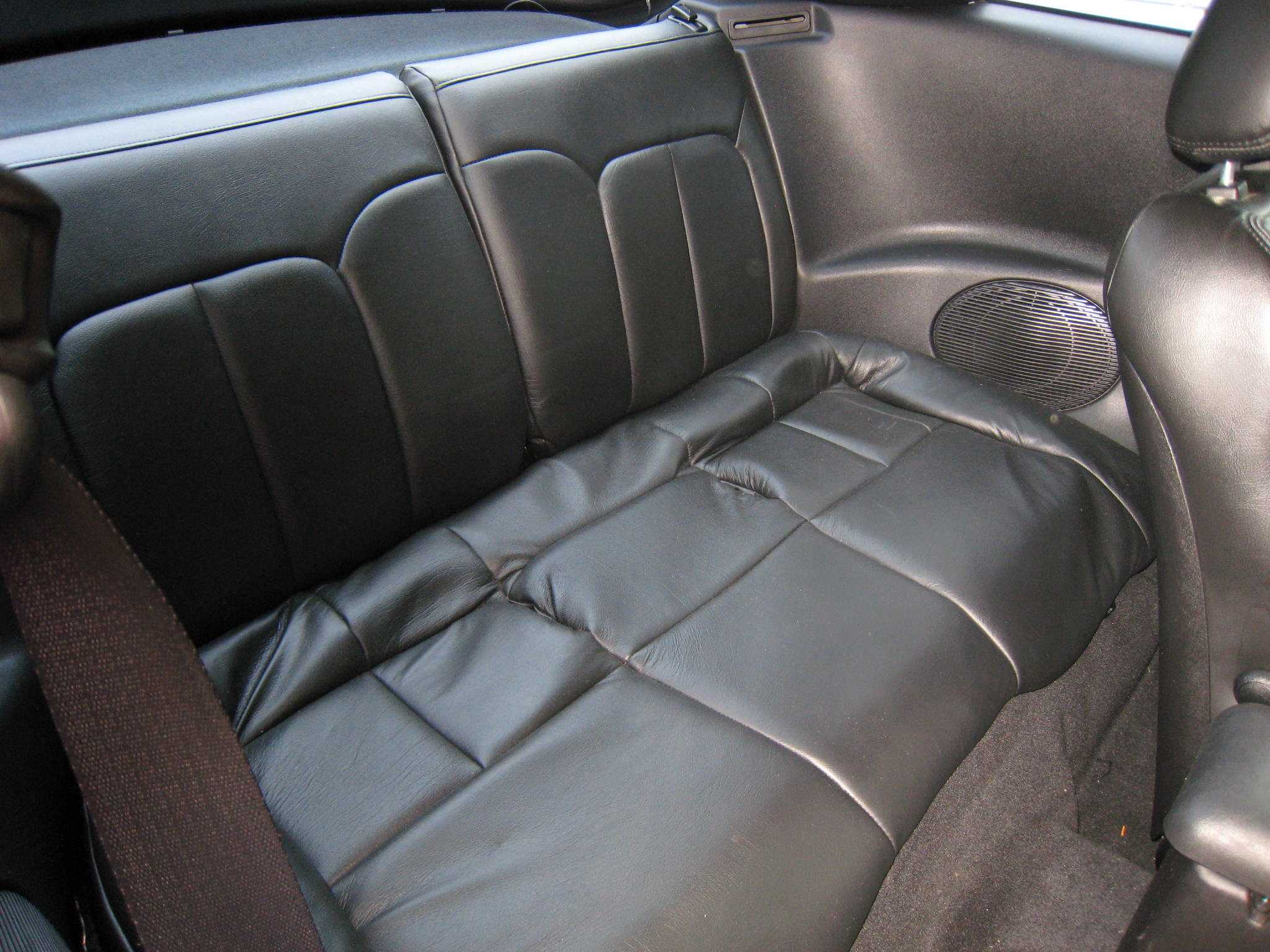
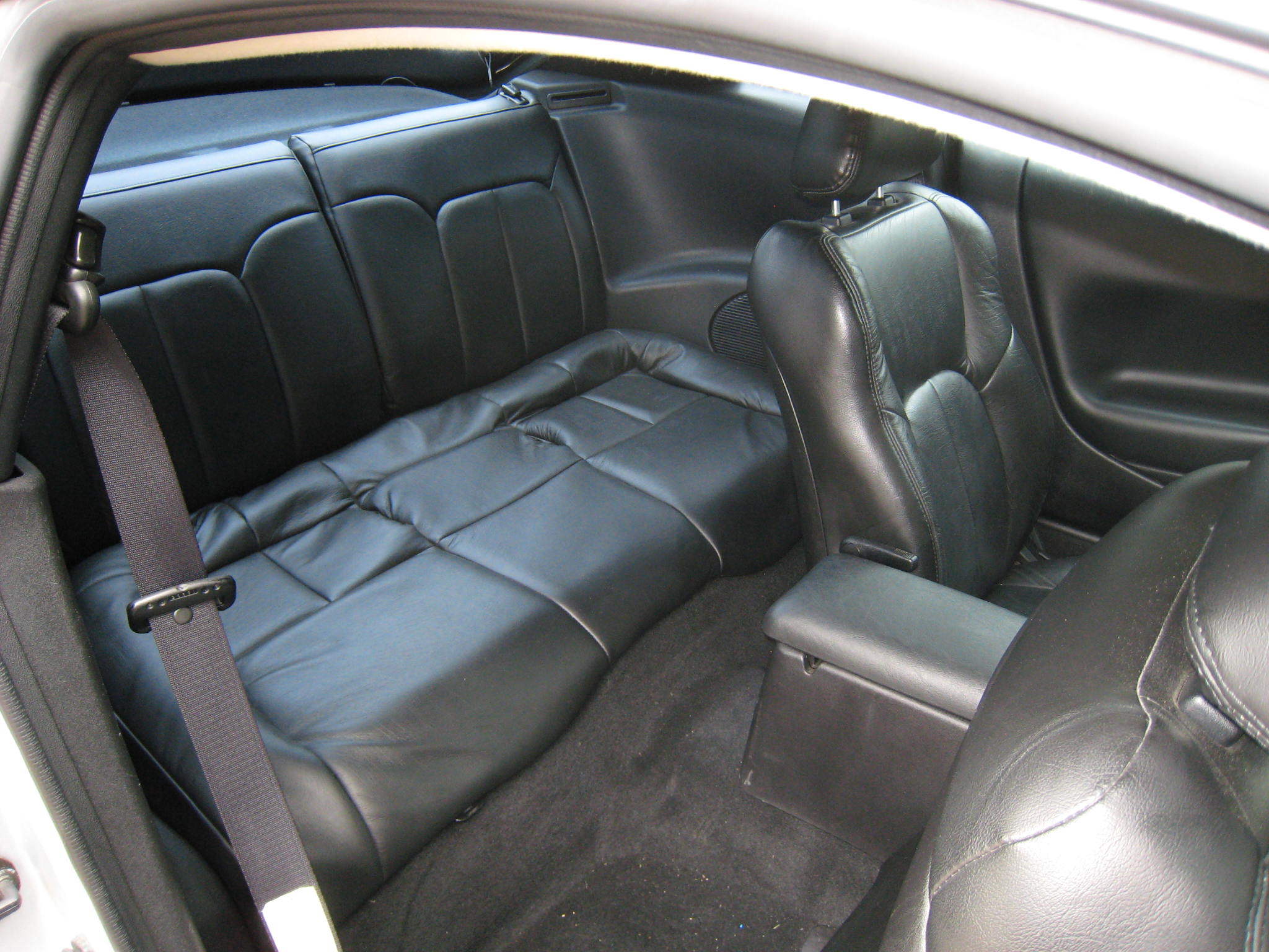
Seating: Two passengers, full leather interior.
Large rear leather bench deck, behind front seats (which covers the mid-car battery box) |
|
|
----------------------------------------------------------------------------------------------------------------------------------------- |
|
| Step-0: Locating a "Donor Vehicle" | |||||
| To begin a conversion, one must locate a suitable donor vehicle. This is the vehicle that will be converted from gas-powered to electric-powered. Prime candidates will be small, very light, aerodynamic, and low to moderate in cost. If a somewhat low mileage vehicle, say with a blown motor, can be located... that would be most preferable. | |||||
 |
 |
 |
|||
|
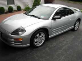
The initial intent was to sell the
Eclipse, which at the time had 50K miles, and had been very well maintained,
and always garaged. However, with the economic down turn of 2008,
serious buyers for a mint+ condition auto where not to be found. Although not ideal due to its weight, the Eclipse became
my donor car because I was not going to give it away. I also did not want to
end up converting a high mileage unknown vehicle. And the Eclipse did meet a
few common criteria... It was aerodynamic, low to the ground, and would fit
an 11" motor. So the Eclipse was the choice! For an example of an excellent type of donor vehicle, and a great story on going overboard, see the White Zombie (aka, the Blue Meanie) at plasmaboyracing.com
|
|||||
|
Step-1: Removal of internal combustion equipment |
|||
|
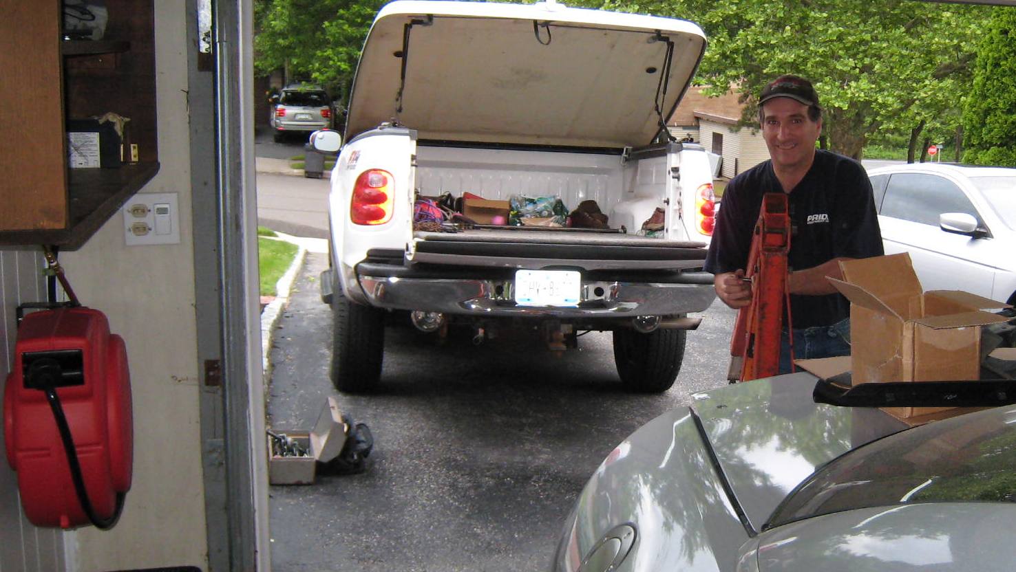
Although many 'conversionists'
remove the internal combustion equipment themselves, the size of the V6
engine, and my humble single car garage made this task quite a chore... So I
took the next best approach. I decided to pay to professionally have
a number of items removed from the vehicle. This is where Joe and Keith,
and Middle Country Automotive come in.
A list of work to be done, including cutting the openings for the battery boxes, was prepared. I was not sure the Joe and Keith would be interested in this work, as they run a very busy shop. So, I decided to drive down and talk with them directly. Before saying much, I handed Joe a list of the tasks I needed done. I clearly remember him reading the list for a bit, before a smile appeared and he looked up and said "And what are you up to?" We discussed the project, and he was very willing to get involved. The following month Middle Country Automotive (in Selden, NY) had the car for about a week. They cut the two battery box openings (Great Job Guys!), afterr removing the each of the following items: |
|||
| 1. the V6 engine (later sold and used in a Gallant that had a blown motor); | |||
| 2. the exhaust system; | |||
| 3. fuel cell (gas tank, fuel pump, filler tube, and related items); | |||
| 4. fuel filler tube and couplings; | |||
| 5. recirculation and pollution control equipment; | |||
| 6. many other tubes, lines, wires, etc. | |||
|
|
|||
|
An empty engine
compartment (soon to
be the motor compartment)... |
|||
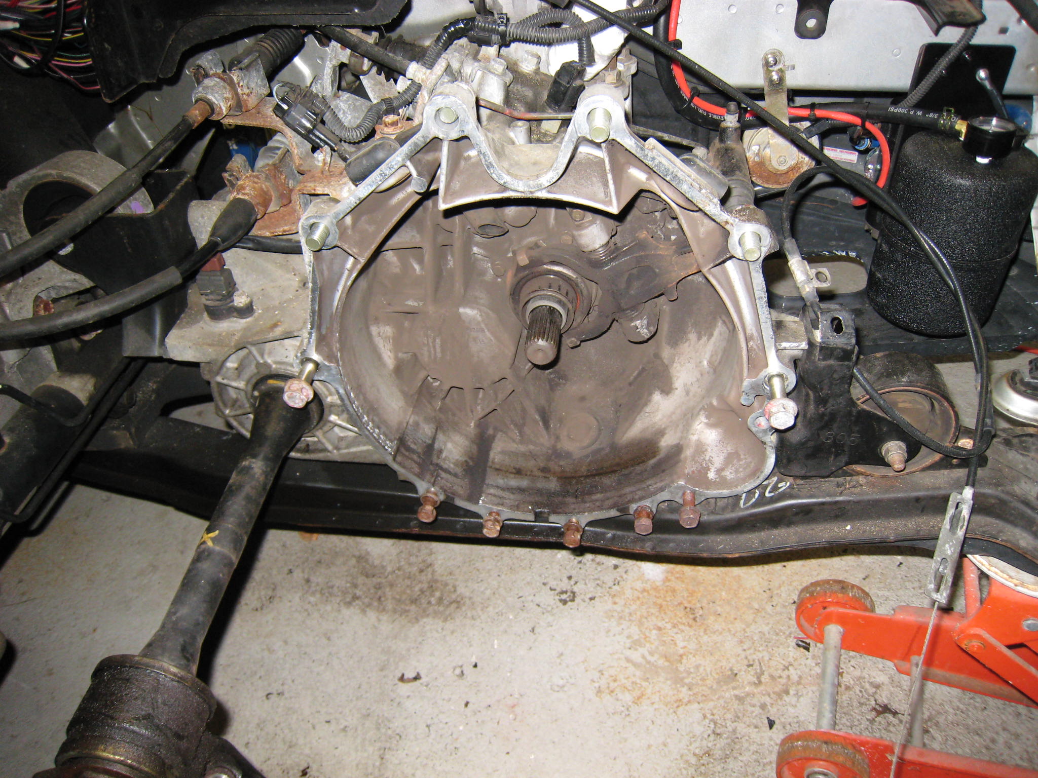 |
Passenger side view
of the transmission bell housing, with the clutch assembly fully removed.
Note the original gas pedal cable (dangling on the right side of the image)
which will be adapted for use with the 'pot-box', and wired to the Raptor
1200 DC high voltage controller. Soon the WarP-11 motor will be mounted to the bell housing, with the original clutch intact.
|
||
|
Transmission Bell Housing (Clutch Assy Removed)
|
|||
| Below, if you look closely, to the left of the bell-housing, in the rear left of the engine compartment, you will notice a dark downwardly projecting item. That is a support structure - formally mounted to the rear of the V6 - which is included to support the passenger side drive axle. Wooo... A bit of a mechanical issue! | |||
 |
This would normally have been a real concern, except I am most fortunate to live near Mike Savino of EV-Propulsion, located in Bayport NY. As you will see Mike did a lot of the hard mechanical stuff. This included mounting the motor (while retaining a fully functional clutch), designing several engine and axle supports, and providing a perfectly centered and mounted motor.
|
||
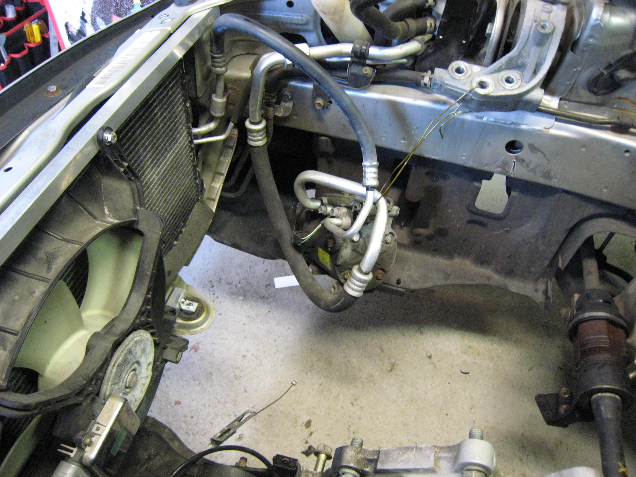
| To the right, an opposite driver's side view
is provided, with axle support bracket shown to the right, and the original AC compressor and hoses
shown in the center. The intent from the start was to keep the AC system if at all possible. It is not very usable (for the most part) with the current lead acid batteries, but will be ready for the future lithium pack. Currently planned for when I find a buyer for the current VRLA pack, or near the end of life of the current pack (say 2 to 3 years). |
 |
|
Step-2:
The Battery Box (BB) Openings |
|||||||||||||||||||||||||||
|
|||||||||||||||||||||||||||
|
|
|||||||||||||||||||||||||||
|
Accordingly, a rear battery box assembly will be
constructed of two "offset" and individual battery boxes. This
somewhat complicated the rear BB
design, but lead to a much stronger and stiffer construction.
|
 |
||||||||||||||||||||||||||
|
|
|||||||||||||||||||||||||||
|
Step-3:
Initial Re-harnessing, custom wiring, and the Ceramic Heater |
||||
|
While waiting for the battery boxes and the custom motor mounting pieces required to install the 11" electric motor, it seemed like a good time to deal with removing the dash board, pulling wires, and installing the ceramic heater element. I had done quite a bit of reading, and found John Wayland's "heater comparison" article to be quite helpful (see http://www.evsource.com/articles/heater_compare.php). So the decision was made to install the ceramic heater directly is the center of the original heater core. Great way to go. Very factory result in that most of the heater and air flow controls can be used as provided from the factory. One small issue. Today's automobiles use heater core elements that are NEVER intended to be serviced or replaced. They are expected to last for the life of the vehicle. Accordingly, getting a modern day heater-core out and back in again... is not for the faint of heart. OUCH! |
||||
|
|
|
|||
|
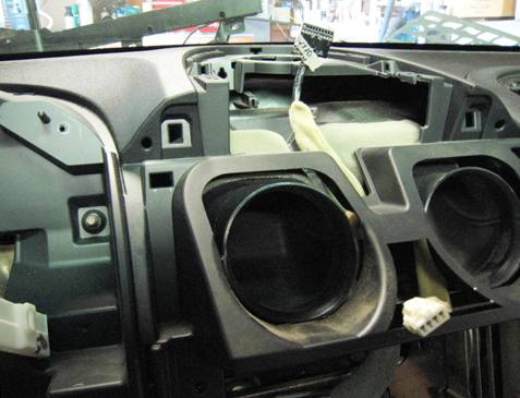
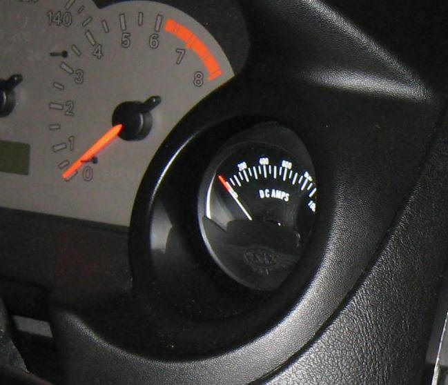
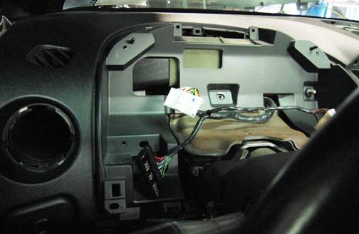
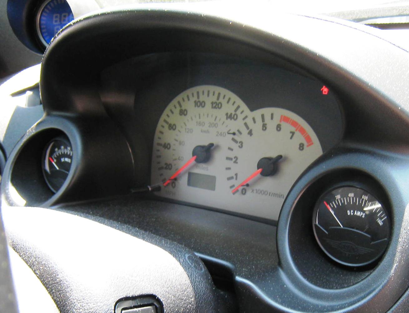
In the picture to the left... The instrument 'combination
cluster' - including the speedometer, the tachometer, and the no longer
needed fuel and temperature gauges - has been removed. The cluster
will be re-worked to include a traction pack voltmeter and an ammeter (in the locations of
the former fuel gauge and temperature gauge, respectively). |
 |
|||
|
|
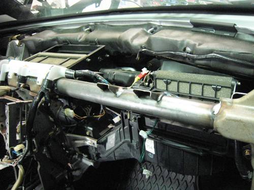
Further disassembly and removal
of dash related items... including center-dash LCD display, air vents,
etc.
After several hours of removing smaller attachments, inserts, and many many screws and bolts, the one-piece shell is now ready to come out. |
|||
|
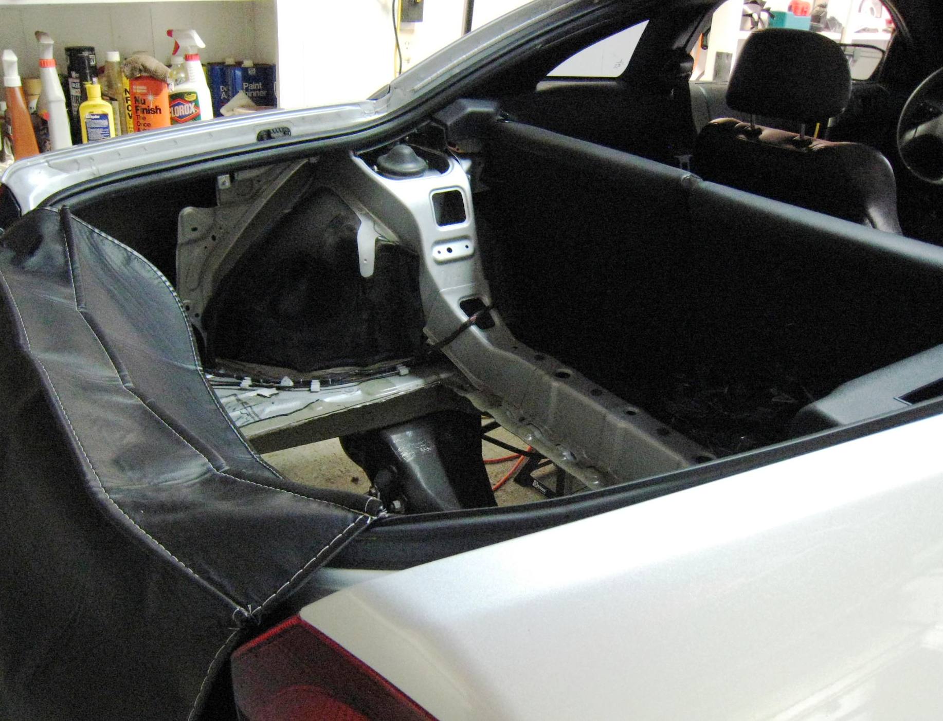
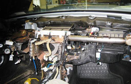
And once the one-piece dash shell is removed (and stowed on
top of the roof of the car), the view of the interior is a bit freighting.
I sure hope the 100+ digital pictures I sporadically took along the way help
to get this mess back together again. However, this was the only
option to get some heat in the car, and to properly pull the many wires that must run
between the soon-to-be motor compartment and the passenger compartment. |
 |
|||
|
|
Hard to believe the pictures above and to the left are the underpinnings of a car's dashboard.
|
|||
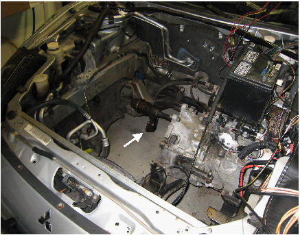
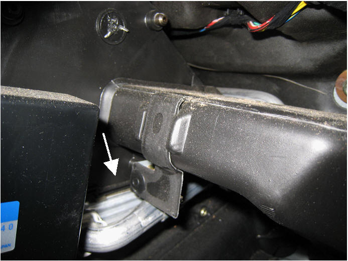
|
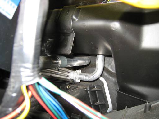
And on the right and below, if you study the pictures, you will see the end-view of a slot, into which the heater core is inserted. The white arrow should help. Note the aluminum tube with the right-angle bend, which enters the close end of the heater core. Next, both of the tubes must be cut, several more plastic duct pieces must come out, an electronic module or two must be removed, and magically... the heater-core is out... And pieces of the dash are everywhere! |
 |
|||
|
|
||||
|
|
||||
|
Before moving on to the installing of the 1500 watt ceramic
heater-element, it was time to pull some
cables and wires.... And start the re-harnessing of the motor compartment. |
||||
|
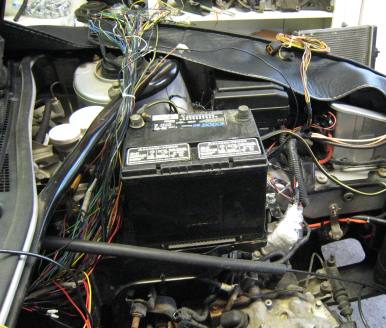
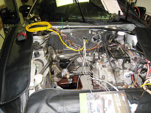
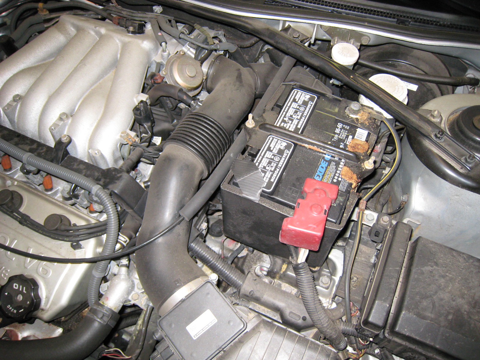
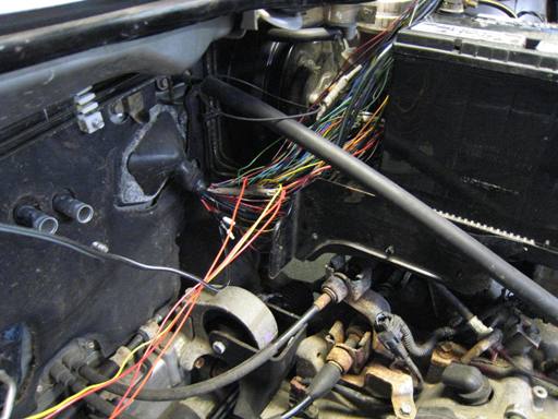
Regarding the image below, and the mess of wires running past the back of the 12V accessory battery, most of these wires will be eliminated.
Why are so many wires no
longer needed?
Well
the original V6 engine had many sensors, including rotation, knock, coolant temperature, air temperature, air
pressure, left bank oxygen, right bank oxygen,... sensors. All of which
required wiring. |
 |
|||
|
|
 |
|||
|
|
||||
|
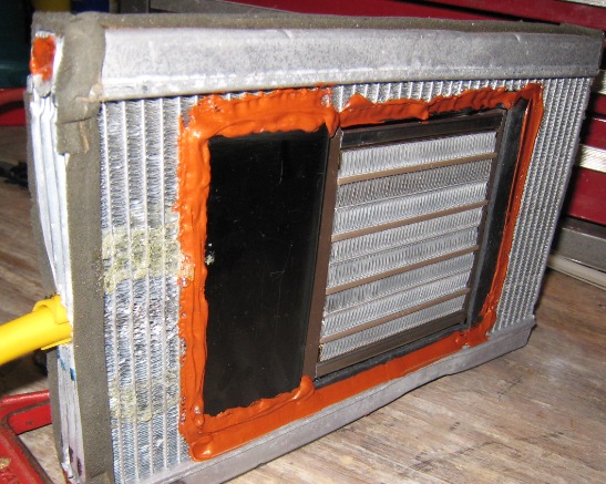
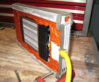
The modified heater-core element is shown on the right, after the 1500W ceramic
heater element is
mounted using a very high temperature (engine
manifold gasket) RTV sealant. The RTV sealant is really tough stuff
that was highly recommended
by a local auto parts store.
|
 |
||
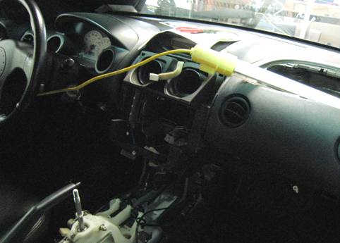
|
|
|
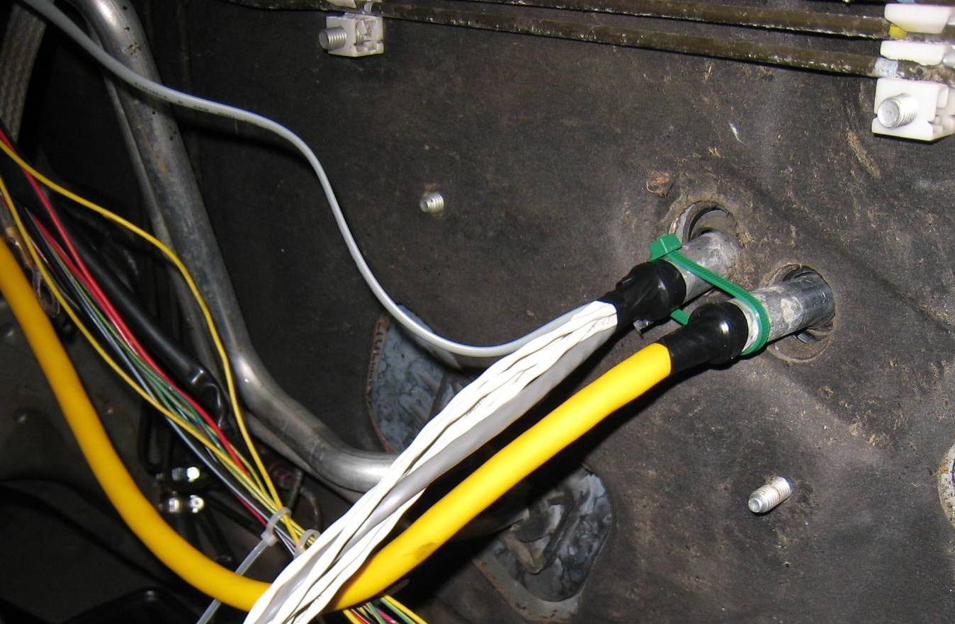
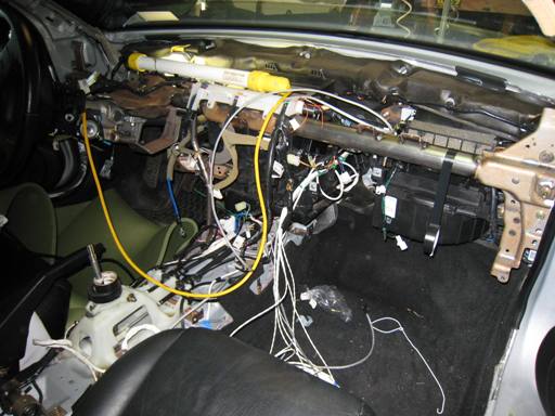
The heavy yellow wire is the double insulated HV cable for powering the heater element. Note that this yellow cable is run into the motor
compartment using one of the original heater core water tubes. The
other water tube was used to pass a group of other wires to/from the motor
compartment. |
|
|
|
From the motor compartment side, the heavy yellow wire will be used to power the ceramic heater element using the full pack voltage. It may be noted that an initial goal for all wiring that is associated with the traction pack voltage (currently ~130 volts DC, nominal), is to provide at least two levels of insulation: a first/primary wrap for each HV conductor, and a second insulating wrap (at minimum). The heavy duty high voltage yellow cable nicely meets this "double insulated" goal. |
||
| If you examine the above image, you will notice six white wires that run from the fire wall, and are draped over the front of the car. Four of these will be used for temperature sensing thermistors that are part of the multi-station temperature monitoring display system. When it comes to electric vehicles... heat is the enemy. | |||
|
|
|||
|
Step-4: Additional Components For Power Steering & Power Brakes |
||||
|
||||
|
|
The mounting location for the electric PS pump took a while to determine. An initial goal was NOT to have the electric PS pump near the rear of the passenger compartment due to noise considerations. I wanted to mount it up front as far as possible. But that idea was not workable. The first issue with a forward mounting location was the need for a very long high-pressure hose to run from the output of the pump to the power steering assist unit, which is located low and close to the firewall in the engine compartment. Second there was no suitable and open location to mount the pump unit. |
|||
|
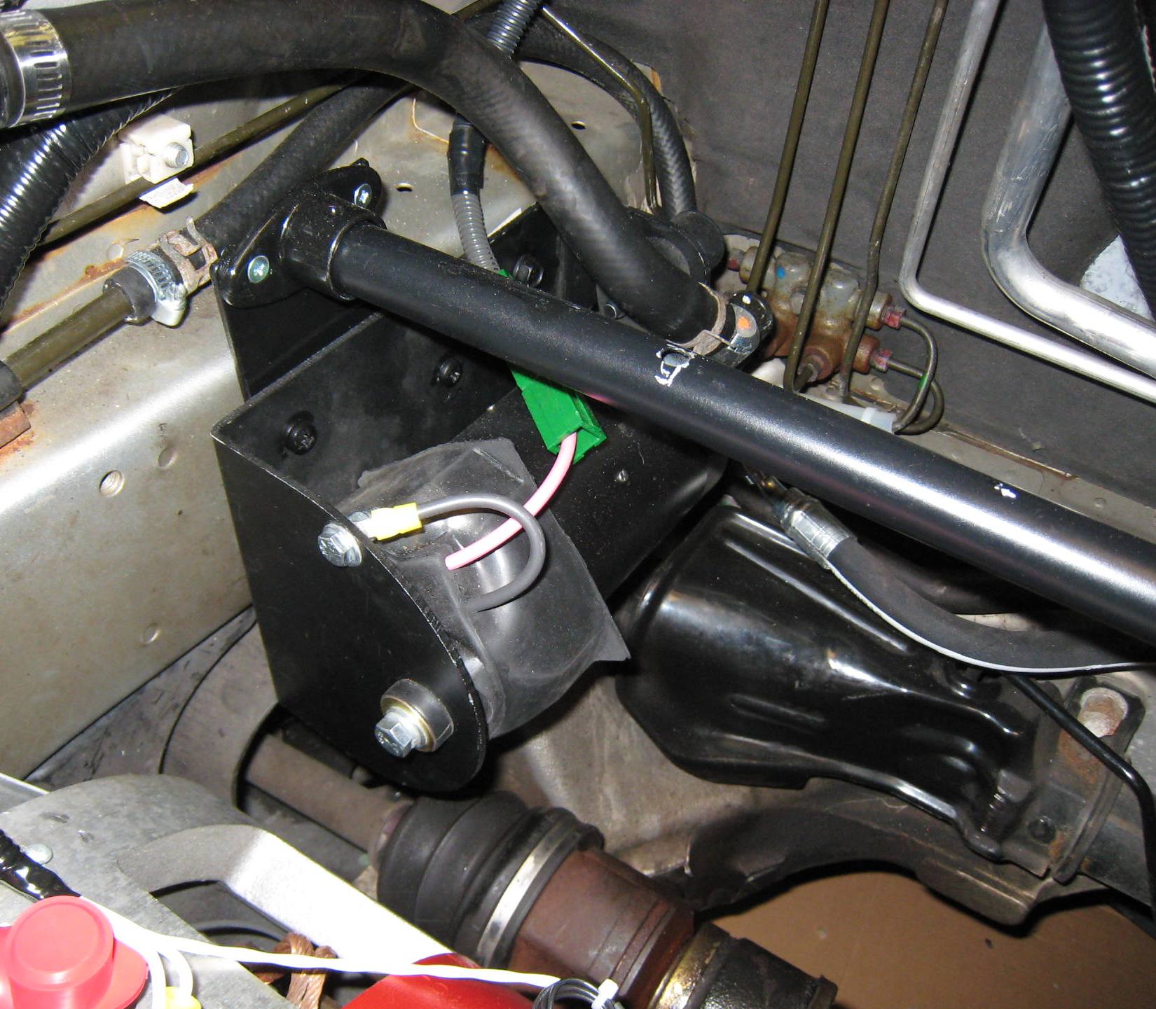
But after considering of several workable locations, the electric PS pump was mounted to the frame of the car, on the passenger side, near the firewall. This location, as shown, meant that only about a one foot long high pressure hose would be needed, and additionally made the electrical wiring quite short. |
||||
|
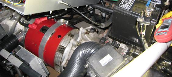
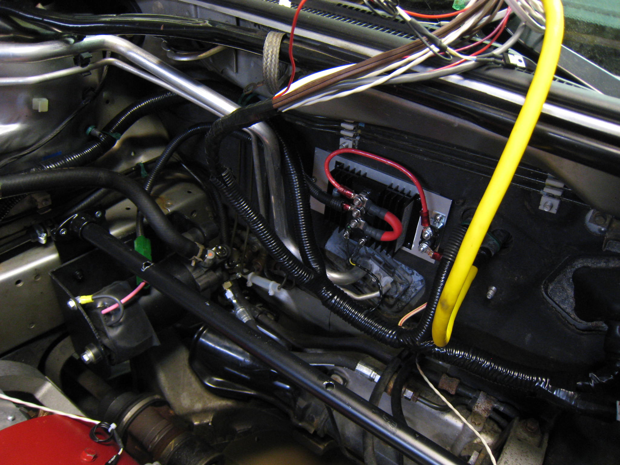
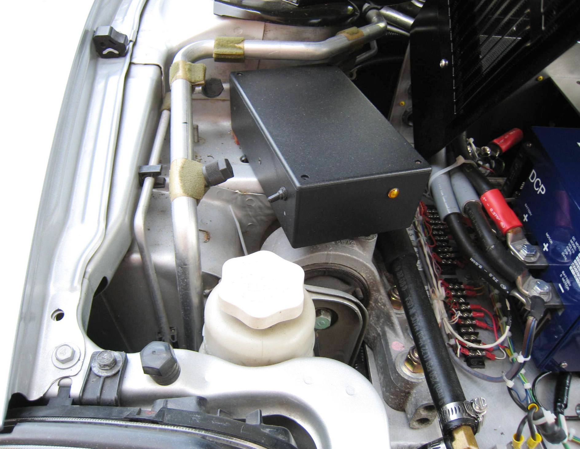
In the picture to the right, you can clearly see the
horizontally mounted PS pump, along with the 1-foot long high pressure line
(which is black).
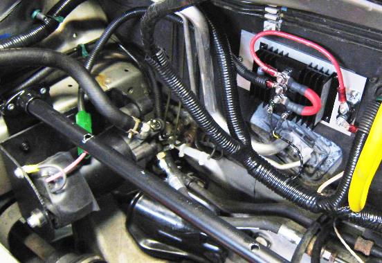
In the upper right of the picture, an item with a finned and black heat sink can be
seen - with the heavy red wires connecting to it. This unit is the solid state relay (SSR)
that will be used to energize the PS pump. |
|
|||
|
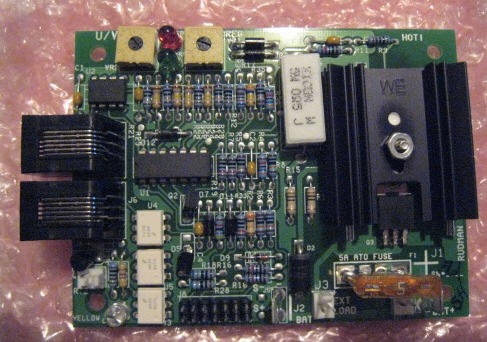
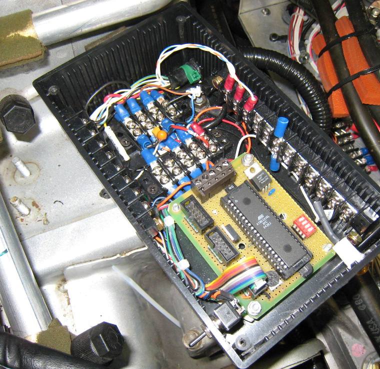
A custom PS controller will be employed to turn on and off
the PS pump based on several different input sensor signals (and
activities). A prototype of the PS controller is shown to the right.
This micro-computer based PS controller board clearly has not yet
been implemented on a printed circuit board (PCB), and
must also be updated to include vehicle speed sensing. |
 |
|||
|
Prototype of
electric power steering (PS) pump controller |
||||
|
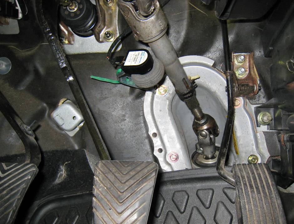
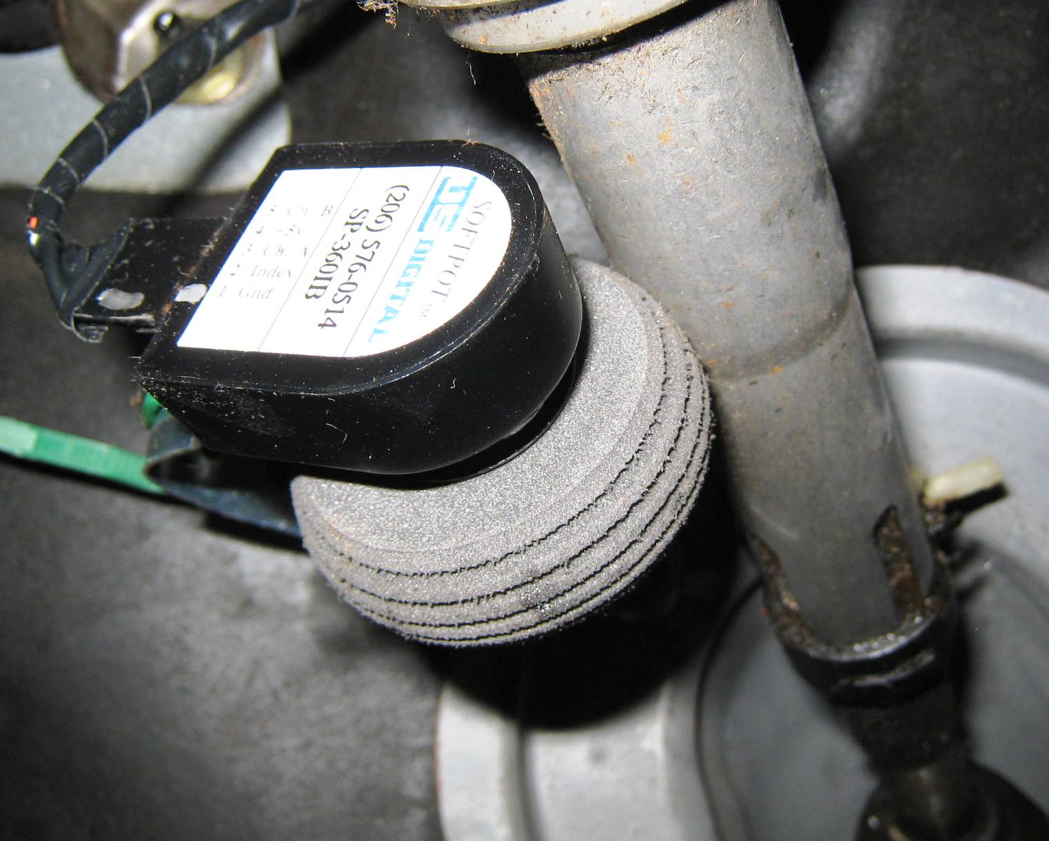
As shown below and to the right, the motion of the steering wheel will be sensed via a rotary pulse encoder (RPG) and a friction wheel arrangement. As can be seen, the friction wheel is arranged for contacting the steering shaft.
Accordingly, as the steering shaft turns, a shaft of the RPG
turns, and the RPG creates a proportional number of pulses. The pulses
are sensed by the custom PS controller (shown
above). |
|
|||
|
|
|
|||
|
--------------------------------------------------------------------------------------------------------------- |
||||
|
Electric
Vacuum Pump and Additional Vacuum Reservoir While reading and studying the quality of EV vacuum pumps (mainly on the Internet), one generally will find a lot of unhappy folks - with less than desirable results being reported as the norm. When it comes to most compact vacuum pumps, they are VERY
noisy. To be sure, the vacuum pump employed on most electric car conversions,
is the noisiest item on the car. If you have ever owned a low cost
electric air pump, useful for inflating things such as pool floats, balls,
and tires... you fully understand how loud these devices can be. |
||||
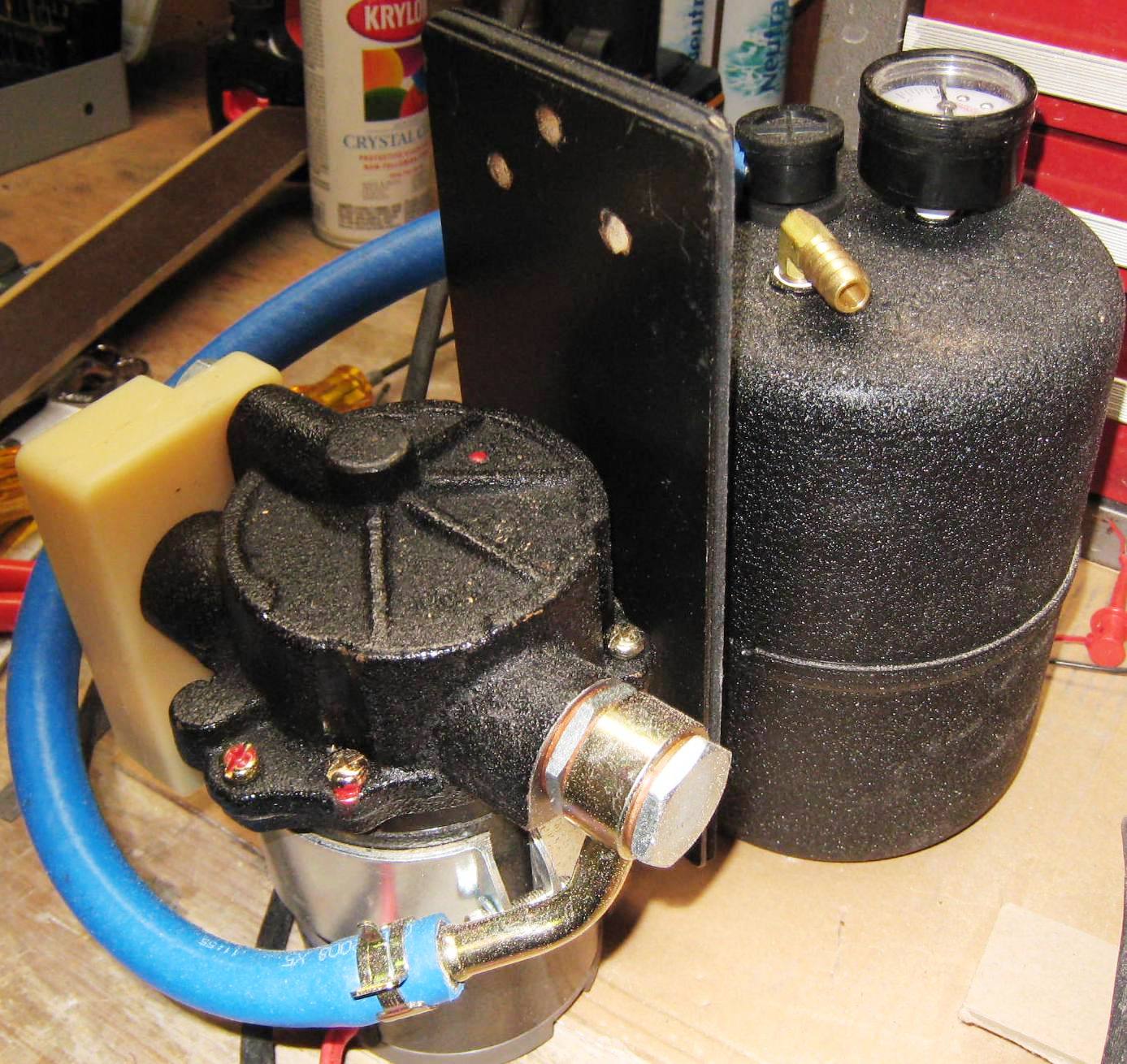
|
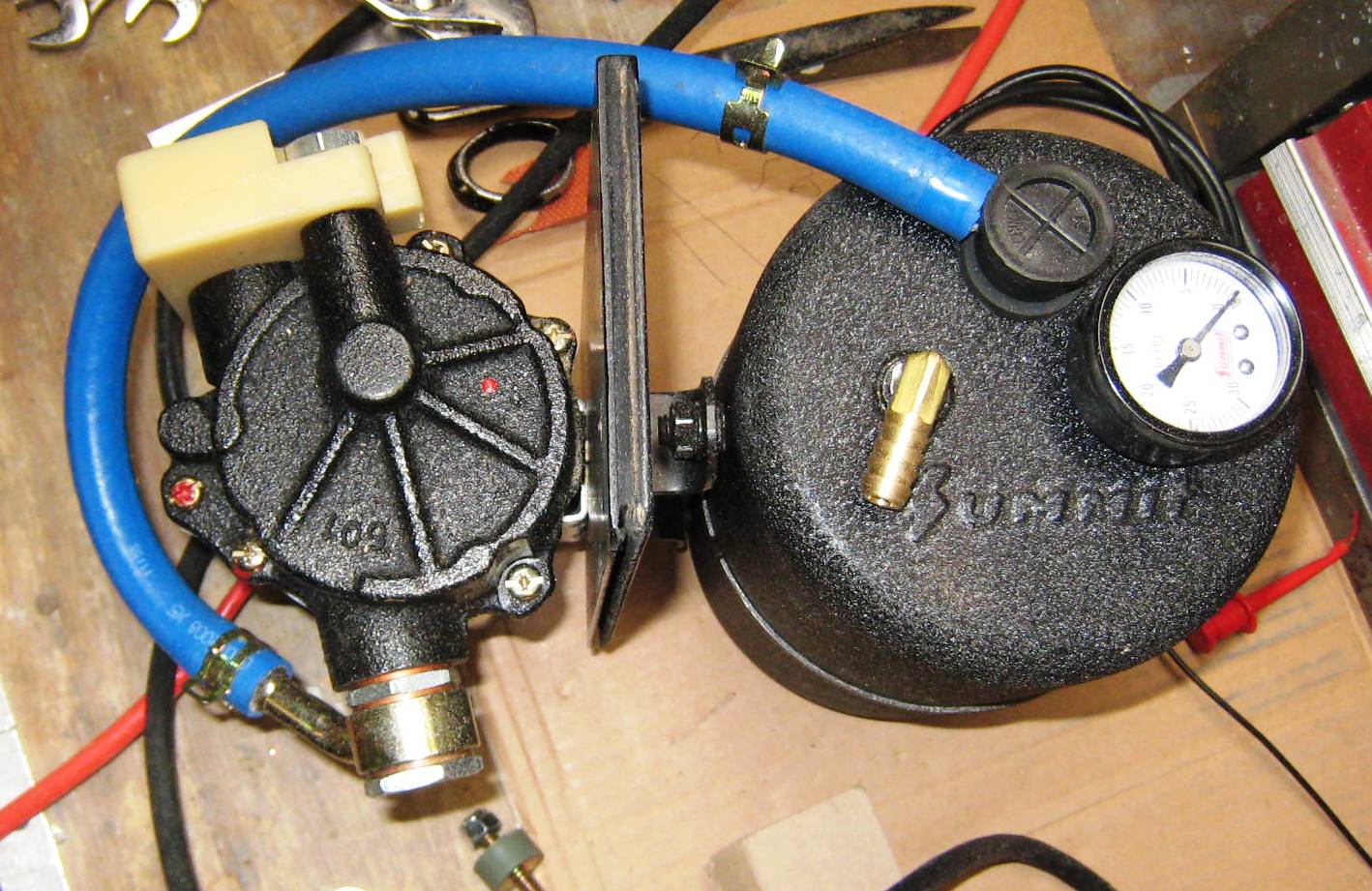
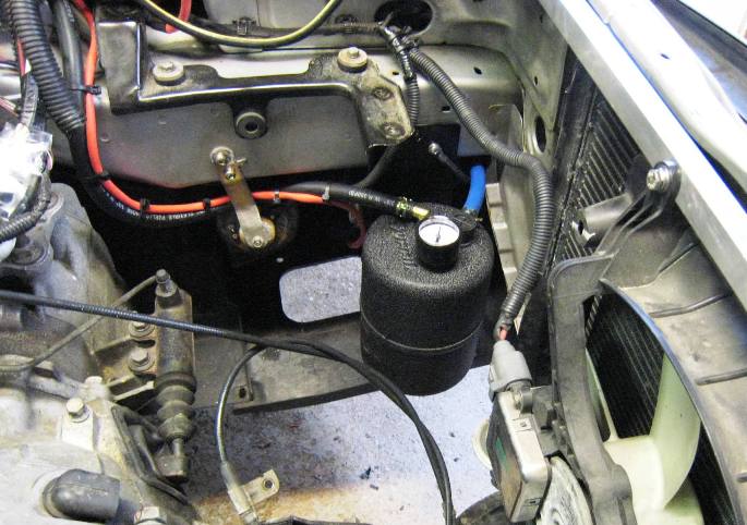
In the end, I settled on a rather expensive pump, that was rumored not to be TOO noisy. Actually it was described as being "whisper quiet" when talking with a sales person over the phone, and comparing them to other known and available units. An additional feature of the chosen vacuum pump, which definitely caught my eye, was an oil filled muffler that was provided over the air intake port. This is the light beige colored rectangular item mounted to the side of the vacuum pump housing. This unit also looked rock-solid, with a heavy casted housing. And this time, I was determined to mount the
pump way up front, and as low as possible. |
|||
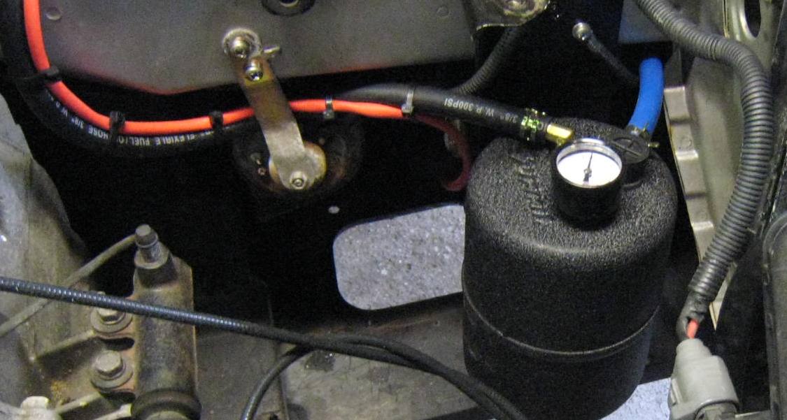
|
As can be seen below, an additional reservoir was included, with a pressure gauge added. All items were mounted to a rectangular plate (black), in a back-to-back arrangement. The support plate is mounted, using thick rubber and floating bolts, to a front chassis support rail, on the Driver's side of the vehicle. |
||||
|
|
|
|||
 |
|
|||
|
|
| Step-5: Mounting And Installing the Warp-11 DC Motor | ||||||
|
||||||
|
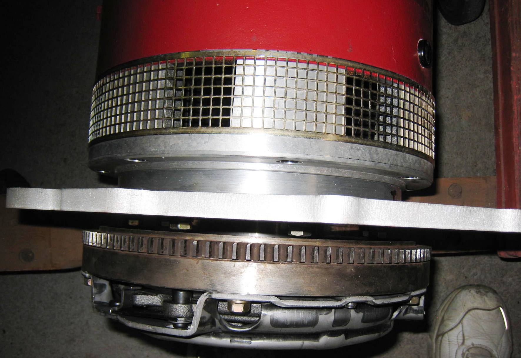
|
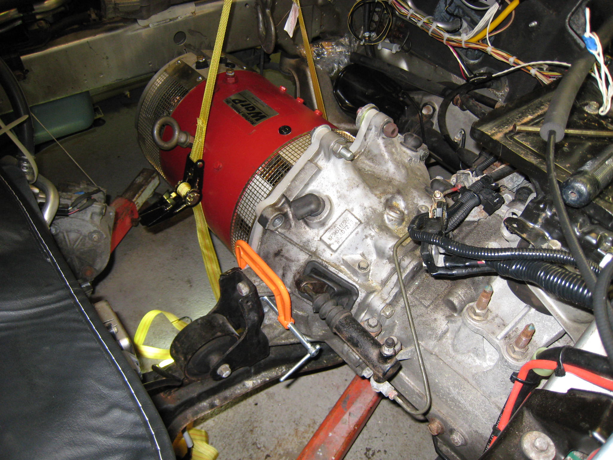
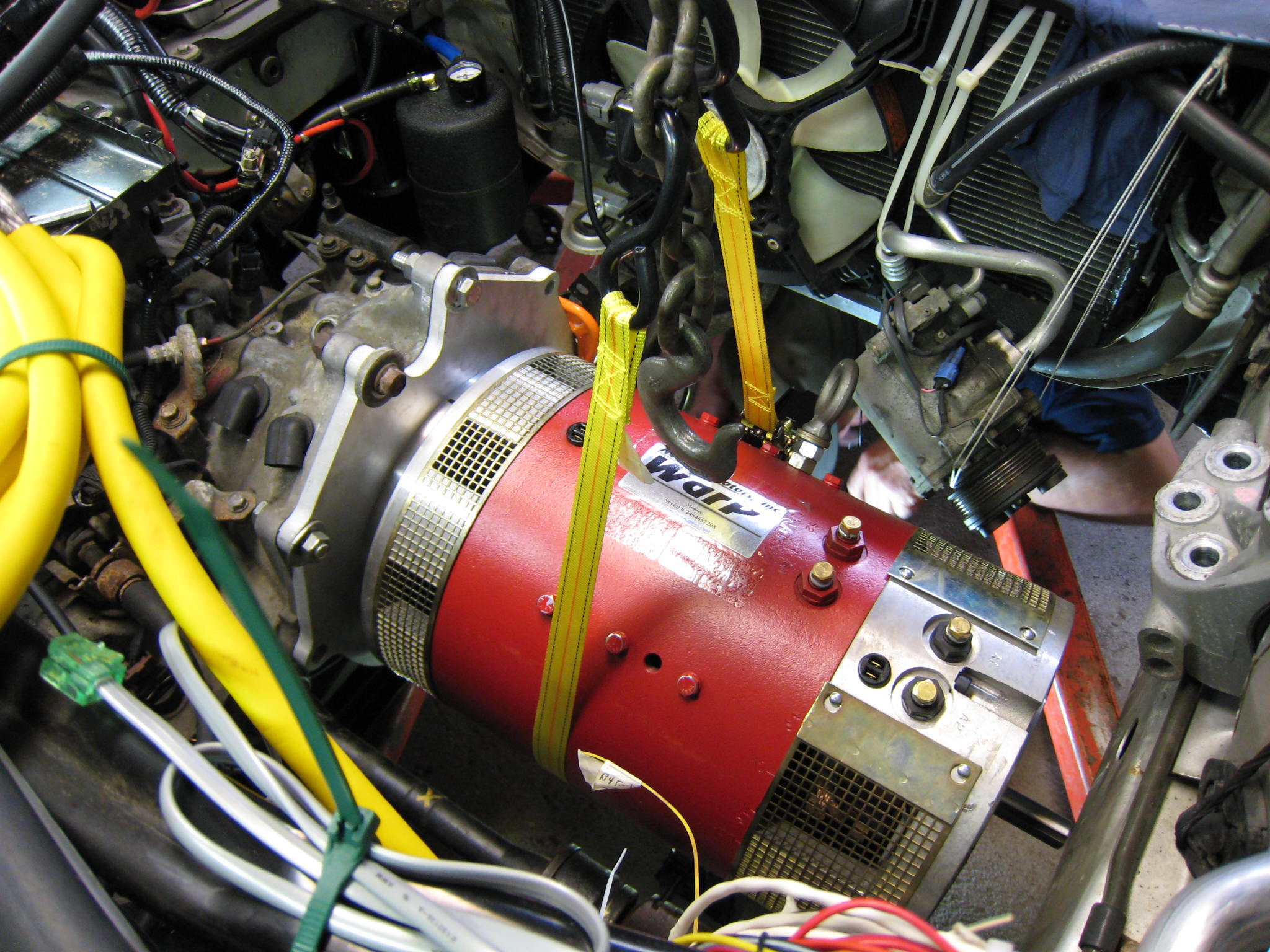
In addition, due to the weight of the vehicle, the 11"
motor would provide the needed torque (and then some).
Mike Savino from EV-Propulsion is shown in the right setting up a hoist for use in lifting and mounting the Netgain WarP11 motor. |
|||||
|
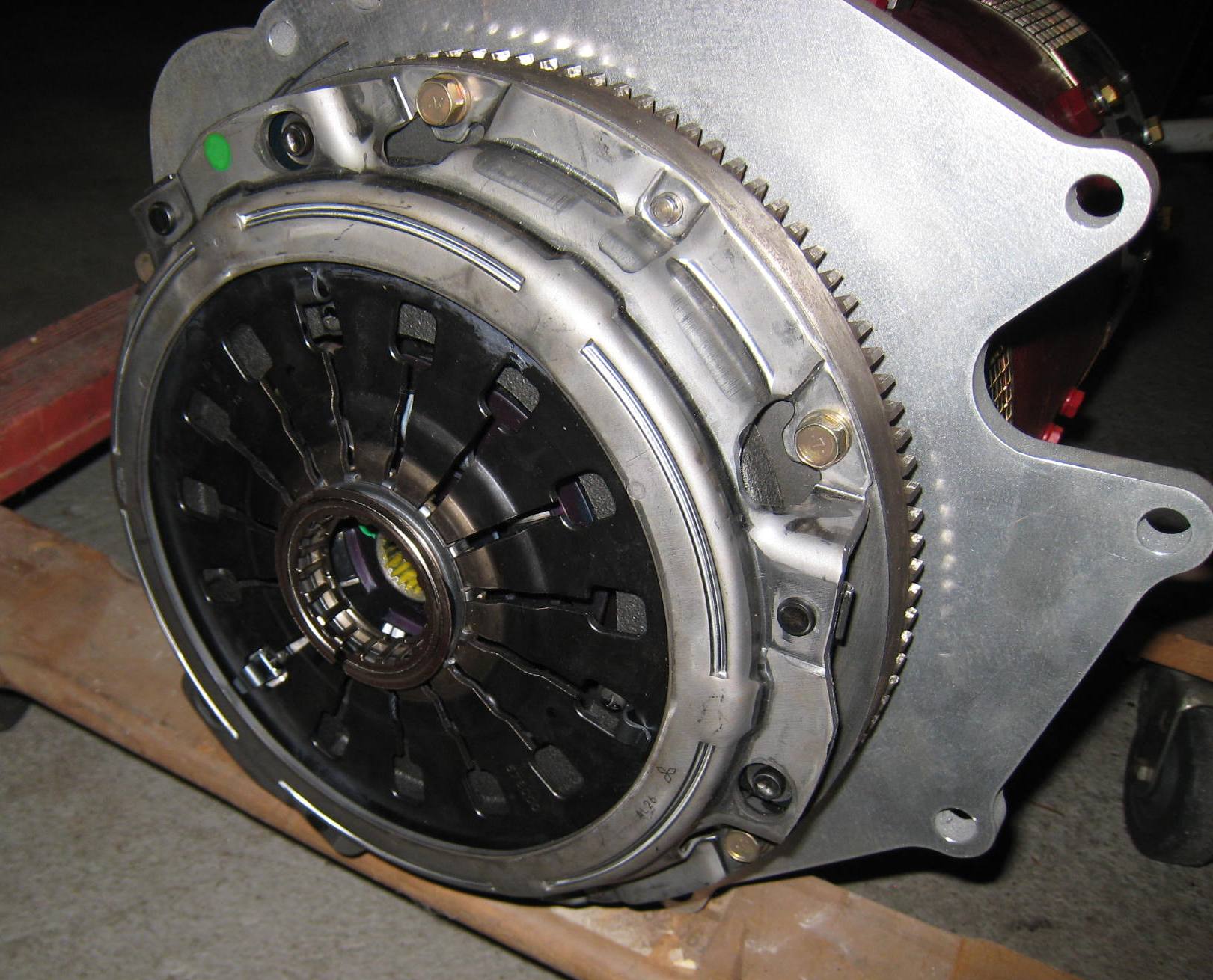
The pictures to the left and below show the clutch assembly mounted to the WarP11 motor. Clearly shown is the custom 1/2" aluminum mounting plate (designed by EV-Propulsion - Great job Mike!), the flywheel and clutch assembly - all fully assembled and ready to be mounted to the original transmission bell housing. |
|||||
|
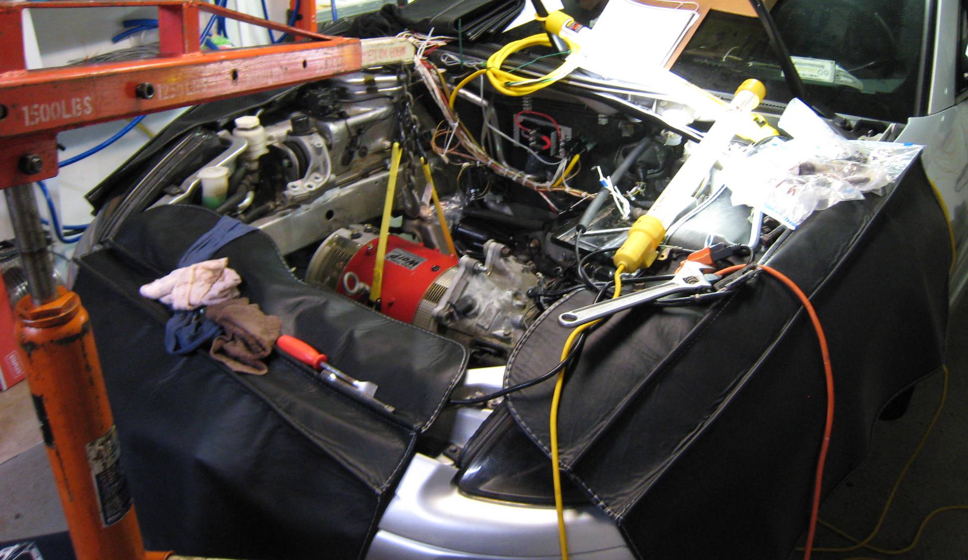
As shown, the motor was initially
installed with several temporary bolts. Although a bit snug, the 11"
WarP motor fit well. Eventually both ends of the motor will be fully supported. |
|||||
 |
 |
|||||
| If you
look closely at the rear of the motor compartment, very close to the
firewall, you can see the main wiring harness (which is not yet re-wrapped with several layers of electrical tape) |
||||||
One of the early decisions regarding the original engine compartment, was to completely re-harness all the under-hood wiring. This was required due to the very large number of wires that were eliminated (and cut back at the electronic control unit, ECU), or had to be re-routed for a new uses. So in the end, wires were added, eliminated, re-routed, with a great deal of removed wiring harvested and re-used during the conversion activities. |
||||||
|
|
|
Step-6:
Additional Motor
Mounting Hardware |
|||
|
|||
 |
 |
||
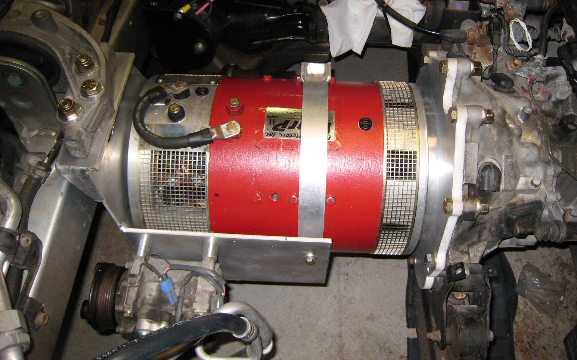
|
|
|
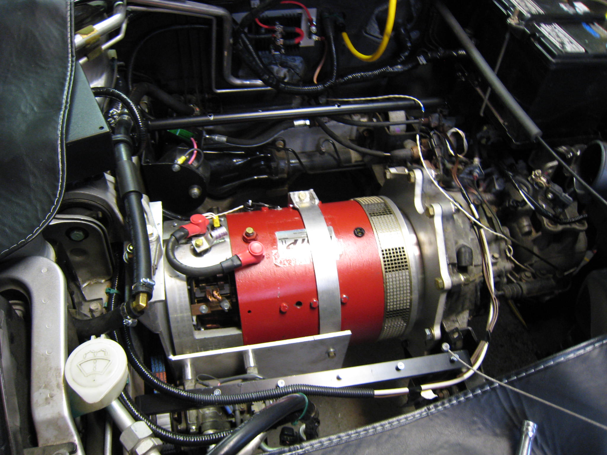
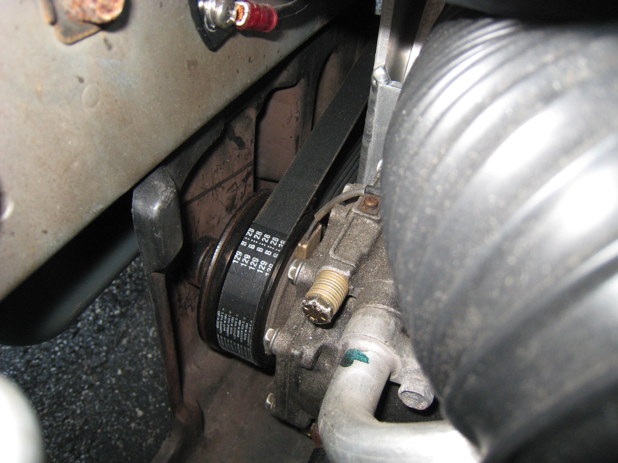
Note that the "tail-shaft side" support bracket, on the back end of the motor, is mated to the original motor mount on the passenger side of the motor compartment. Also, original AC compressor is shown mounted almost exactly where it was originally (when mounted to the original V6 engine).
|
|
|
|
|
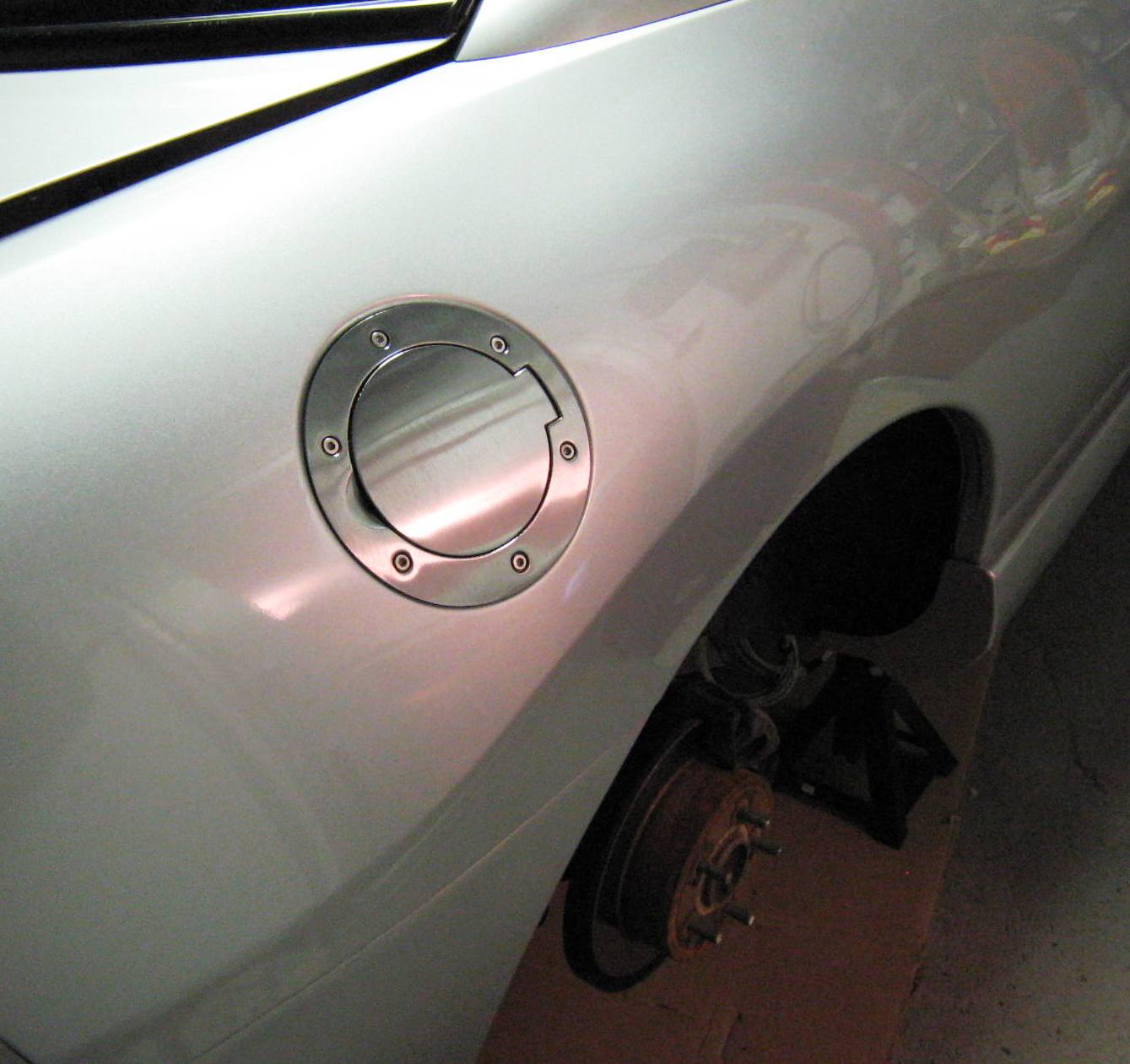
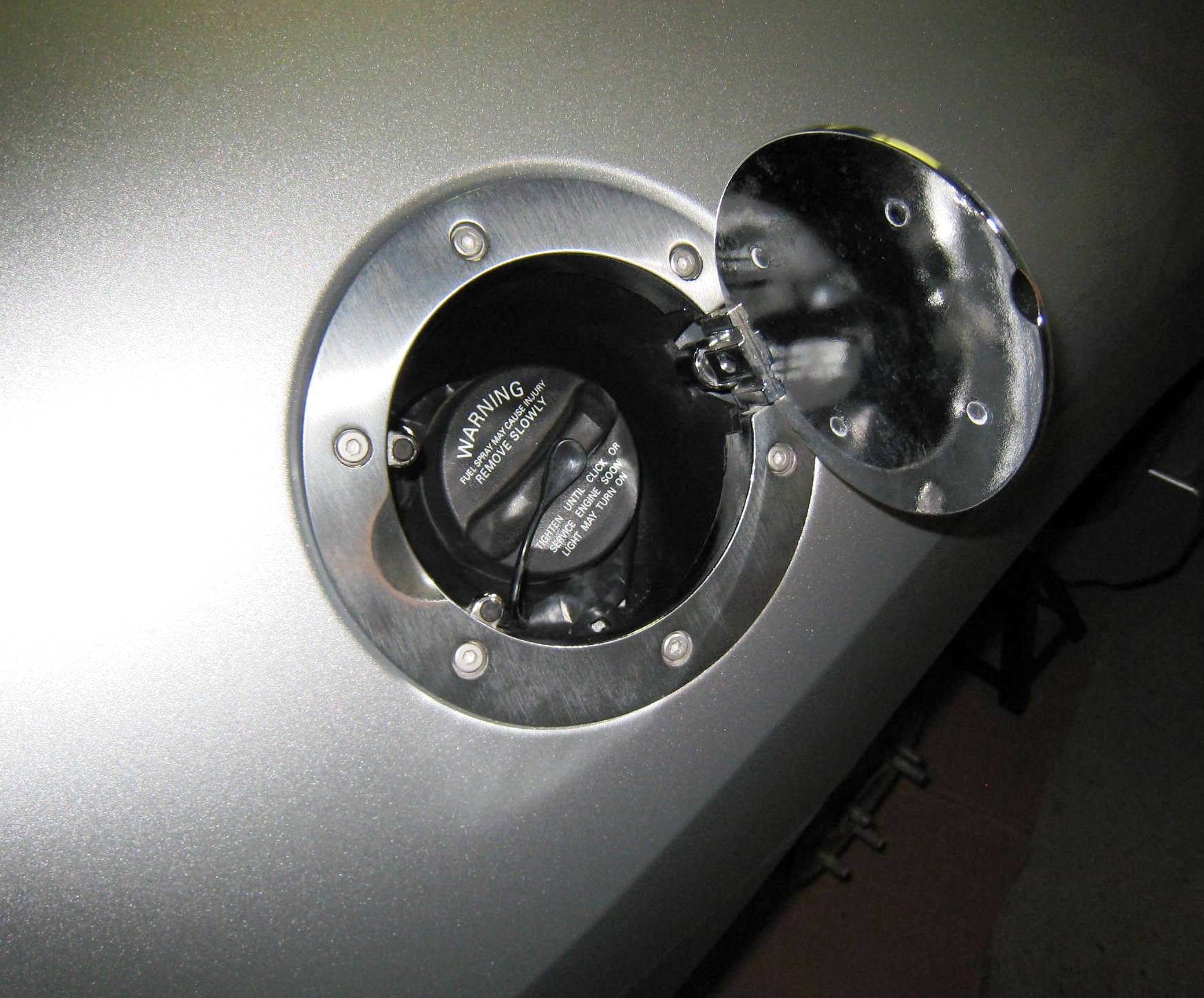
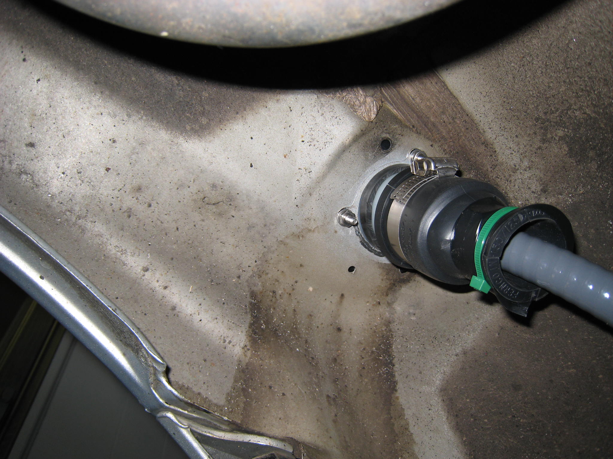
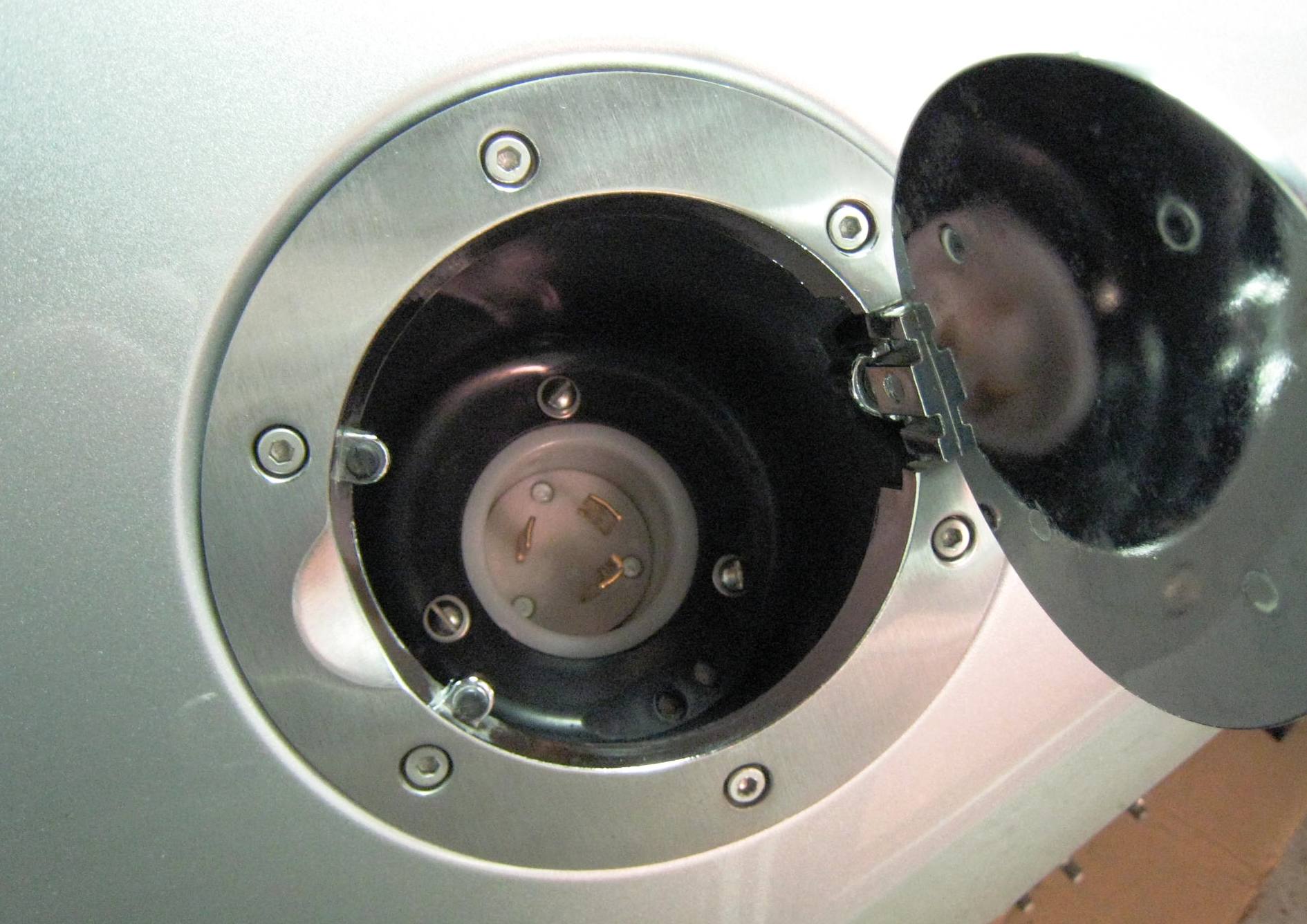
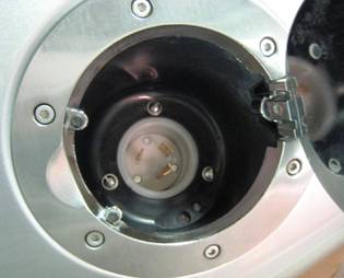
Step-7:
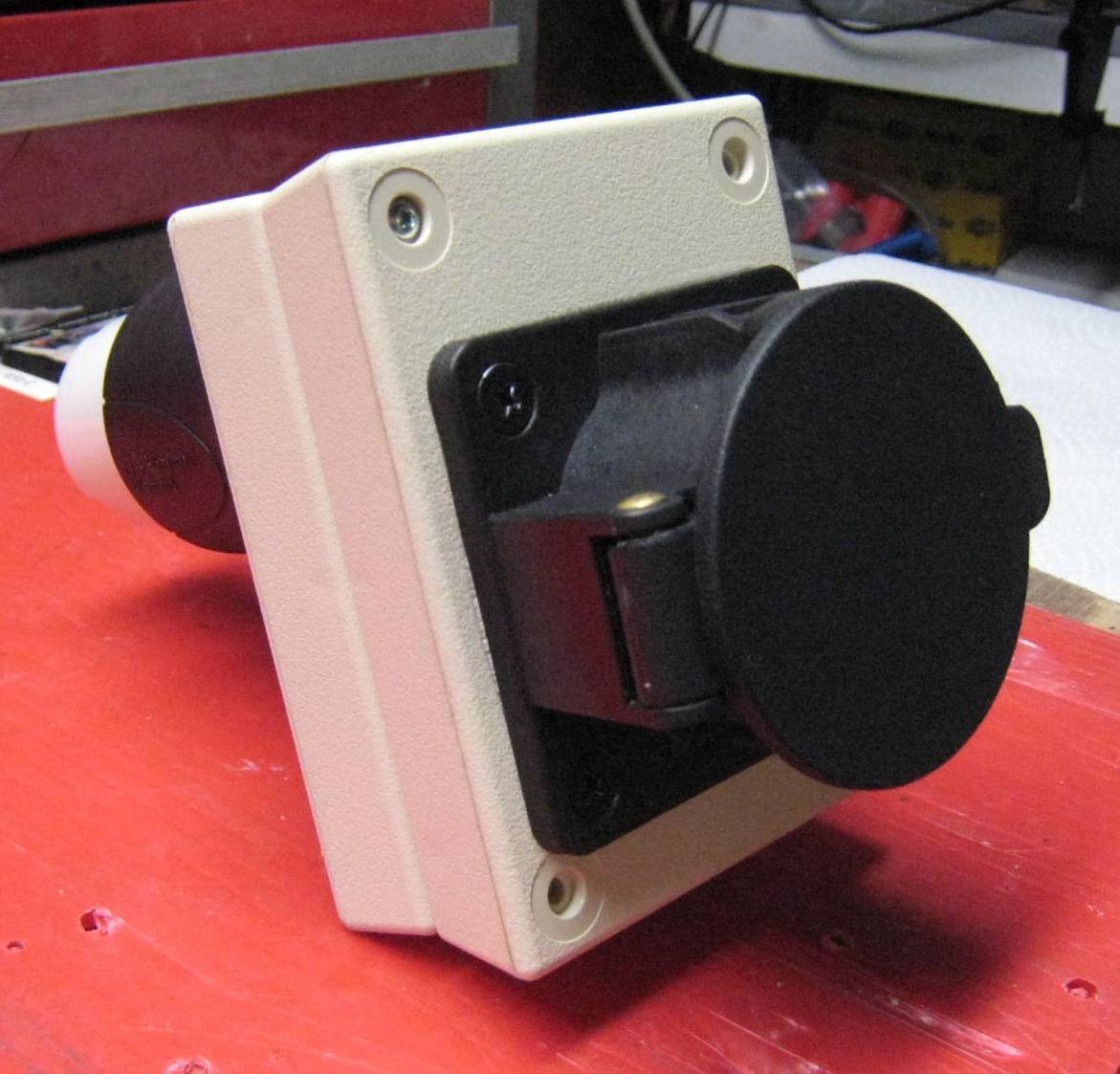
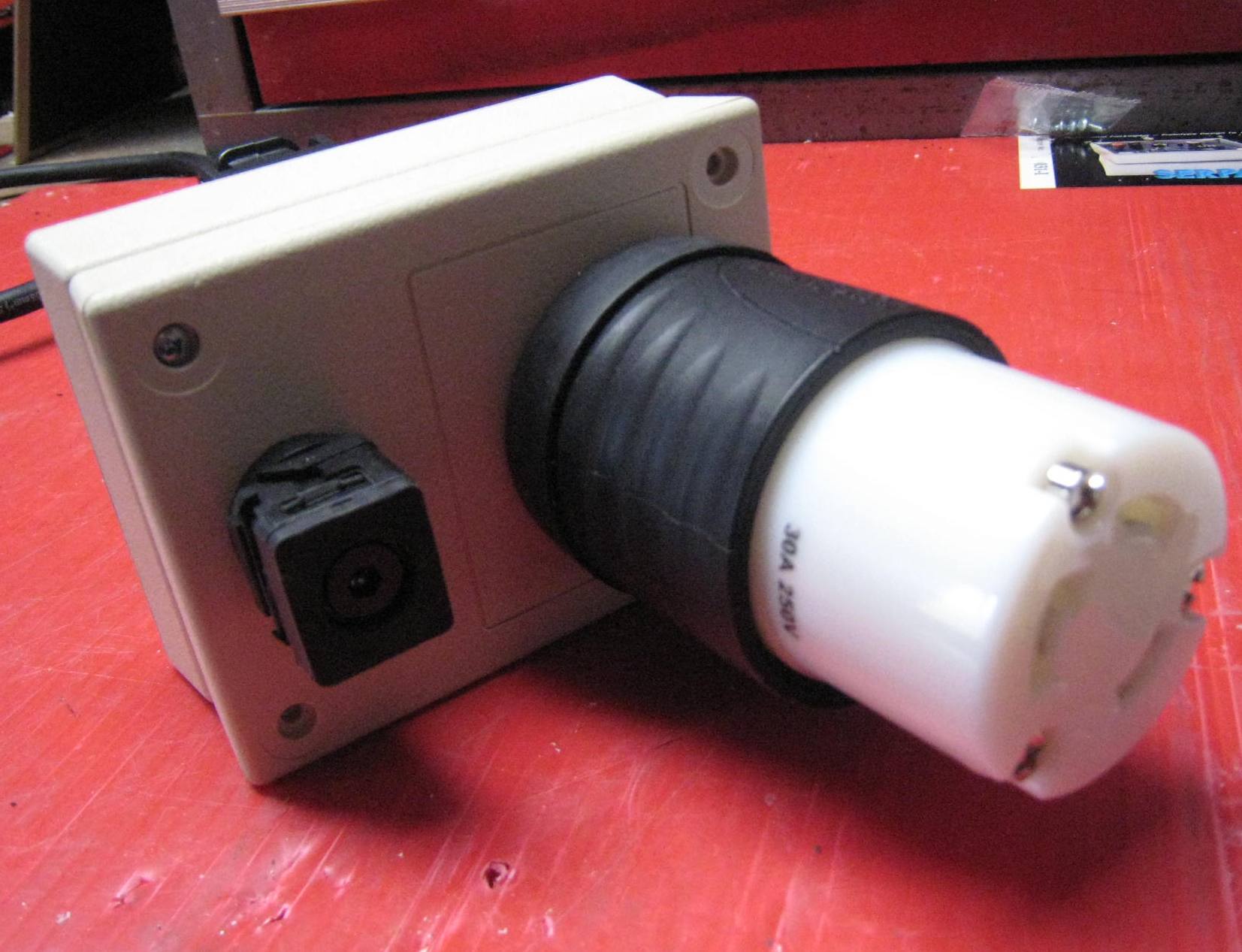
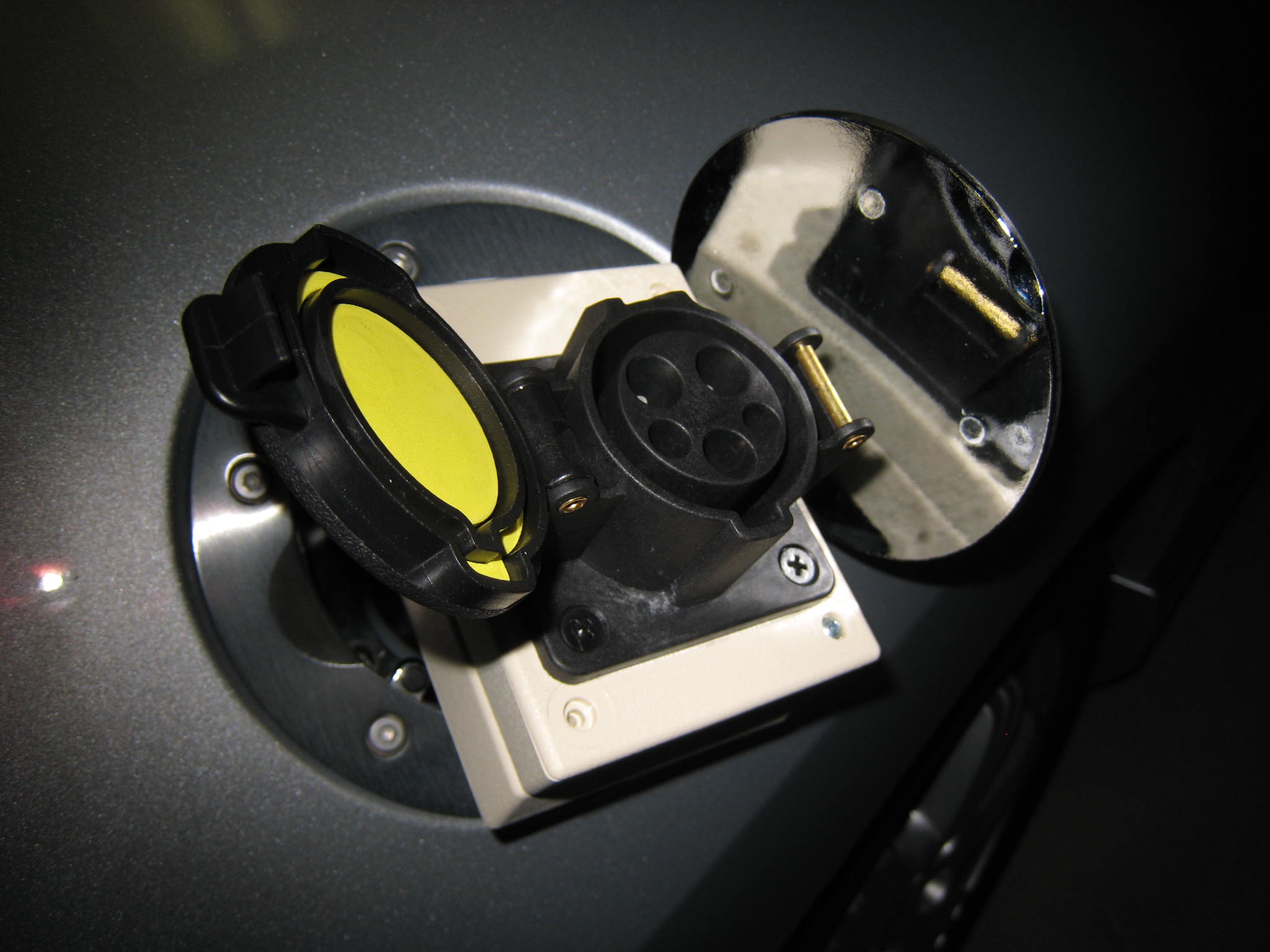
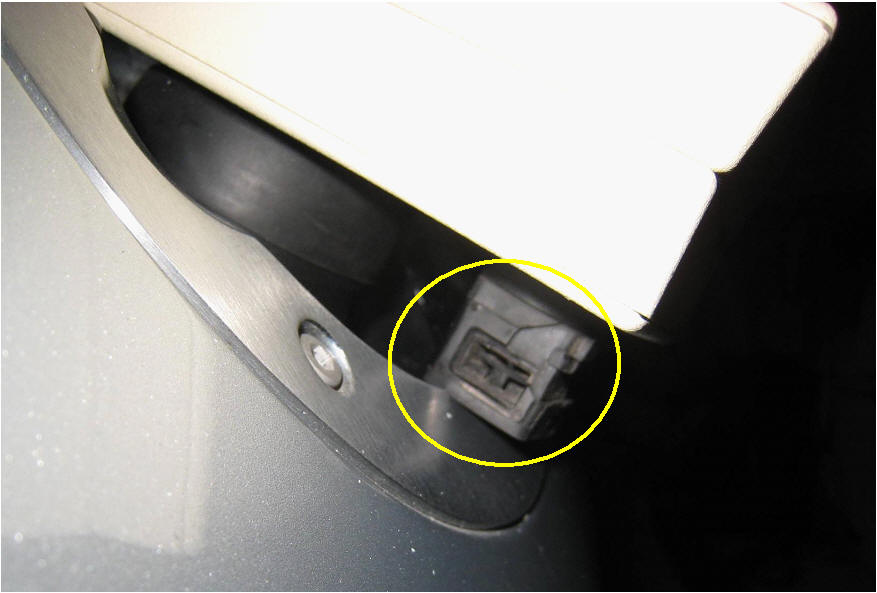
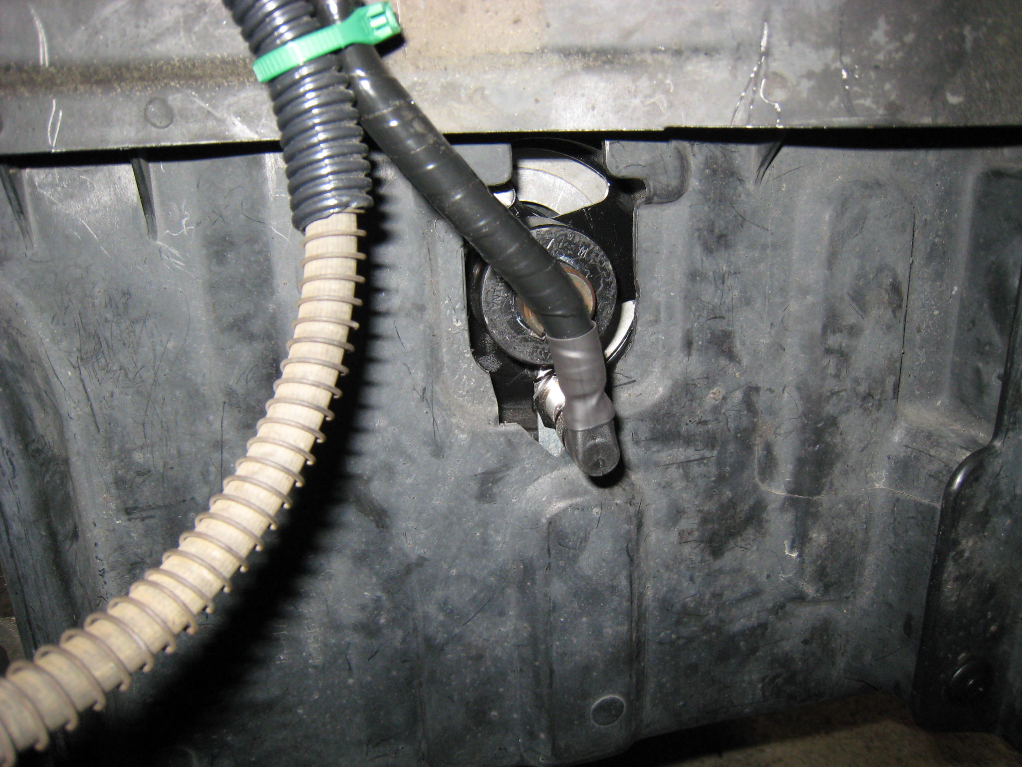
Converting the Gas Fill to a Charging Port |
|||||||||||||||||||||||||||||||||||||||||||||||||||
|
|||||||||||||||||||||||||||||||||||||||||||||||||||
| Step-8: Installing Battery Boxes | ||
| The Mid-Car Battery Box (MCBB) Install | ||
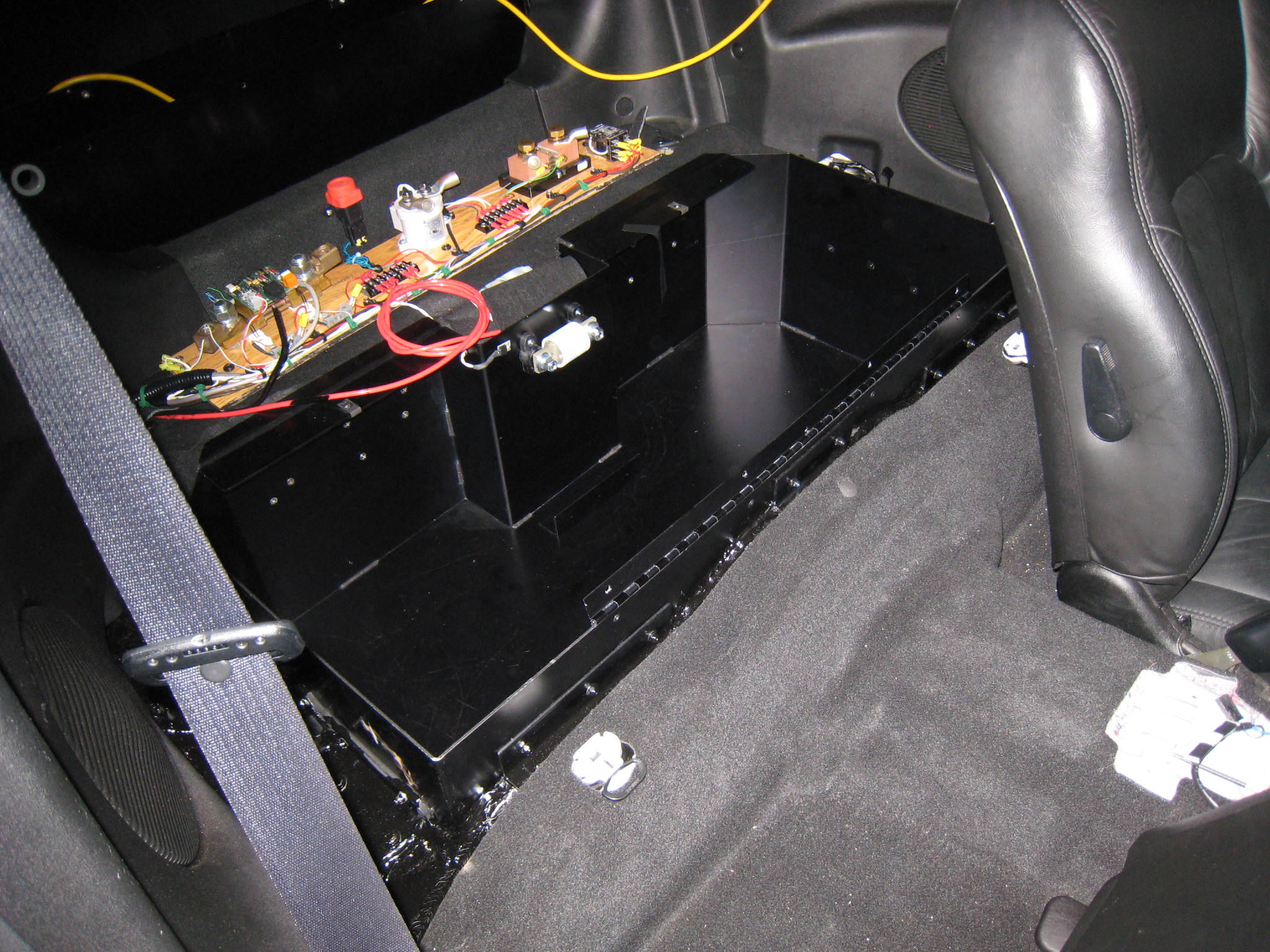
 |
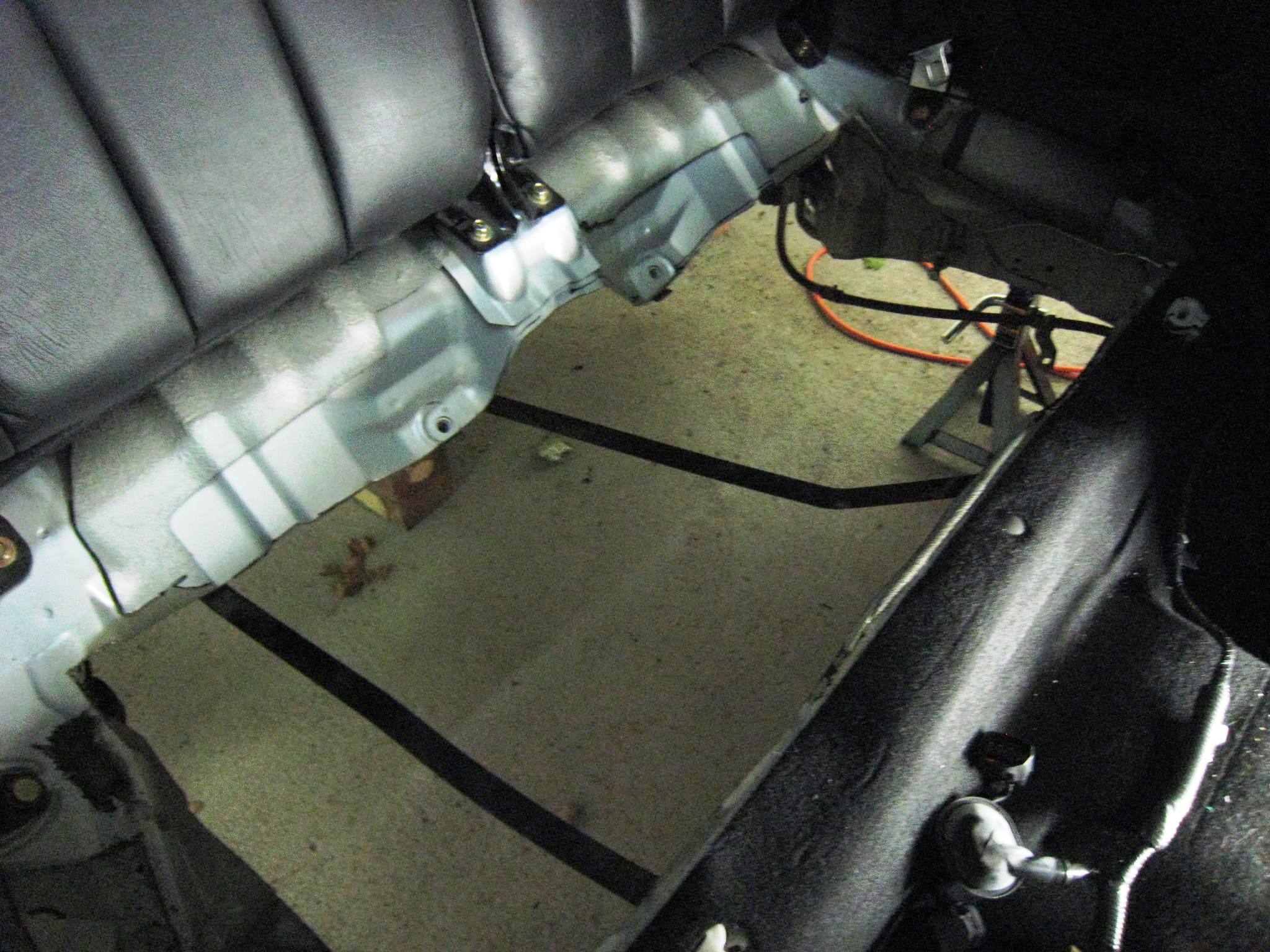
Recall the first battery box
(BB) is
located behind the front passenger seats. This BB is termed the mid-car
battery box, or MCBB. The rough opening shown on the right will be
enlarged a bit - especially in the rear/left side. The MCBB was designed to be about as large as the stock frame will allow. This resulted in the MCBB being fixed to very solid (frame) support structures - on three of the four sides of the BB. On the 4th side - which is the rear/back facing side of the MCBB - mounting support was nicely provided by two spaced 'flaps' bent down and formed by original sheet material of the opening (that was NOT cut away), when this opening was enlarged to fit the below installed MCBB. |
|
|
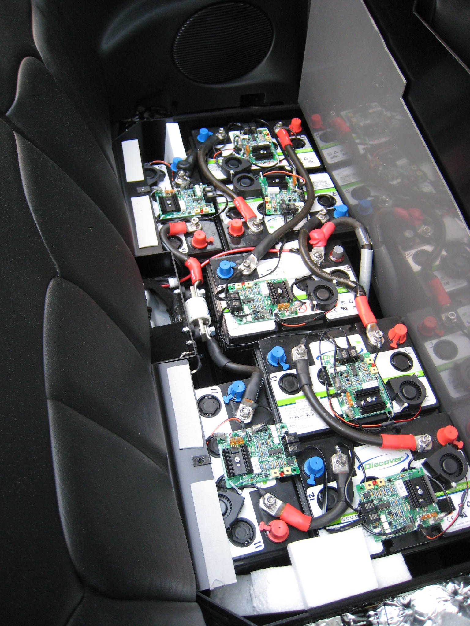
If you look closely at the image to the right, looking at the rear walls of the installed MCBB, you can see some of the heads of the 5mm stainless steel flat-head bolts used to support this rear side by bolting to the flap (hidden from view). Note also the lightly colored "High Voltage Contactor Board", which will sit just behind the original rear seat seatbacks (when later installed).
|
 |
|
|
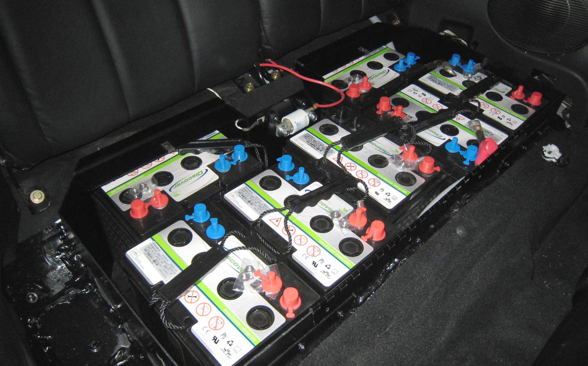
Shown on the left, the MCBB after the EVGC8A batteries were
first installed. It was really really nice to see that all seven fit
just like they were suppose to. Note the white 800A slow blow fuse in the middle rear of the MCBB.
|
||
|
|
|||
|
|
|||
| The Rear Car Battery Box (RCBB) Install | |||
|
The second battery box (actually an assembly) is located in the original trunk area. Both the mid-car BB and the rear-car battery box (RCBB) are mounted as low as possible. This is done for several reasons, including to lower the center of gravity for the resulting conversion. |
|||
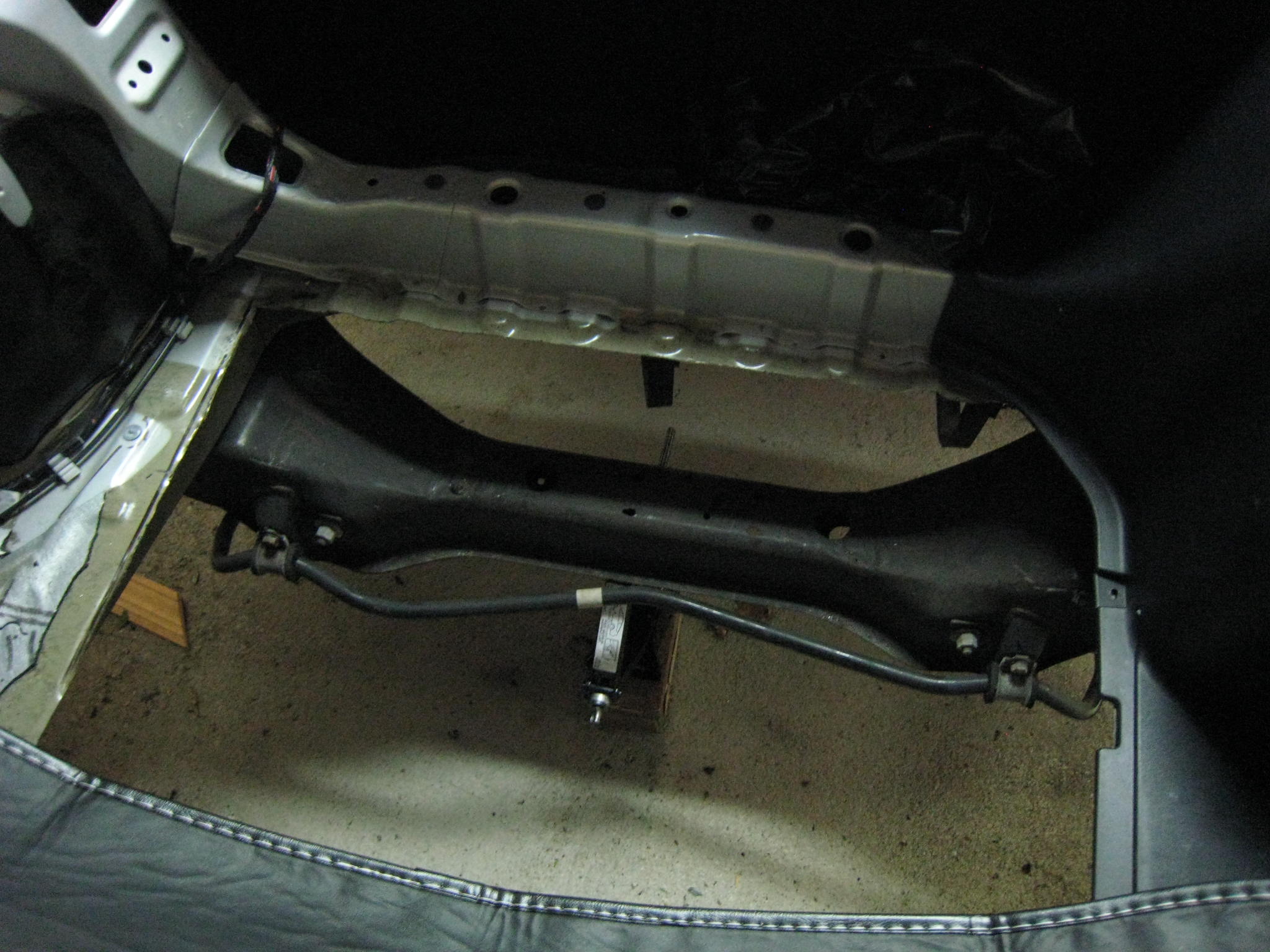
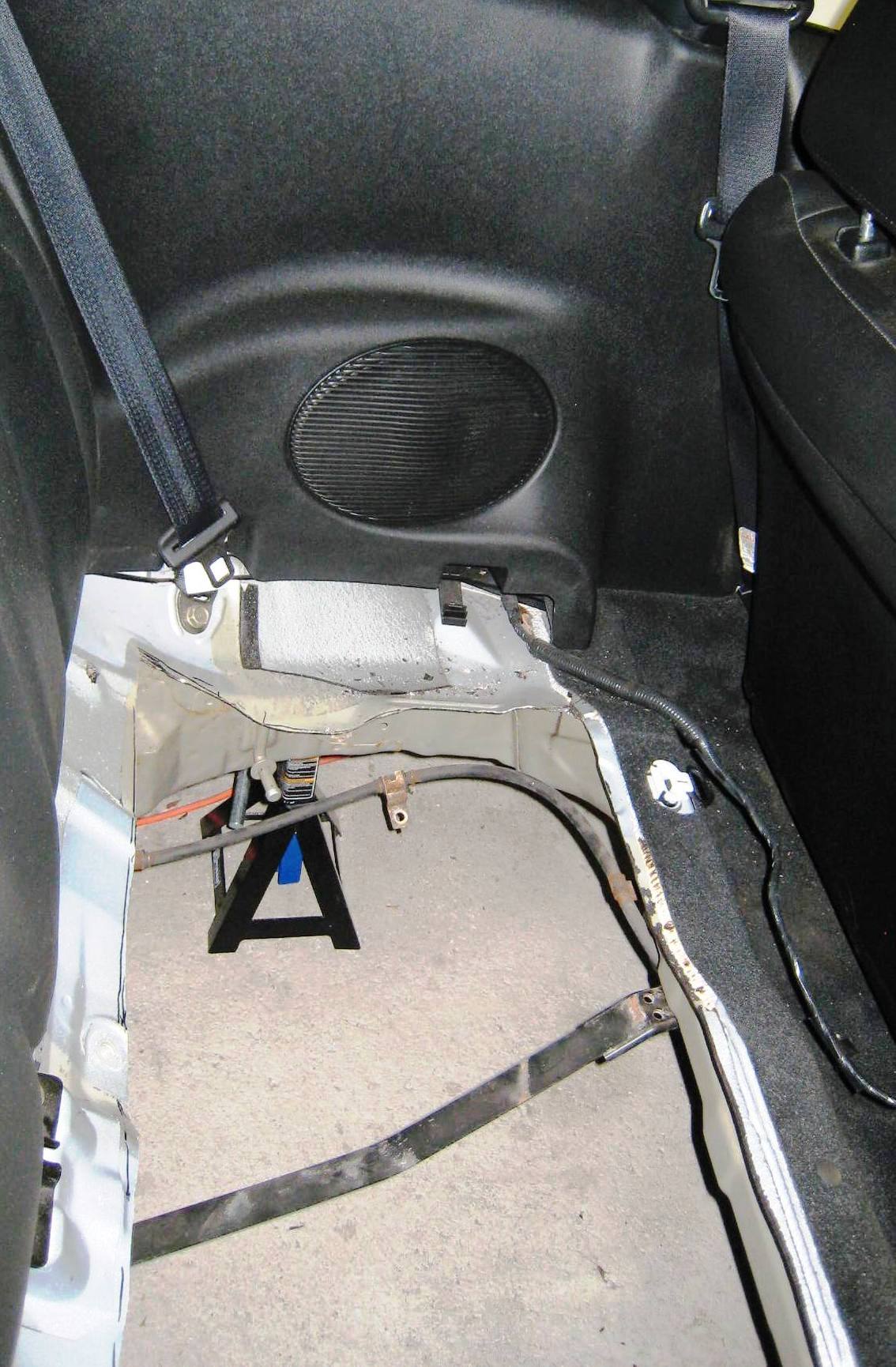
|
|
Recall, when earlier discussing the rear car battery box
opening, there was an issue with the location of the (dark colored) rear
axle support structure, which can be seen in the picture to the left.
Recall further that as a result of the location of this
important structure, three of nine batteries to be located in the rear-car
battery box will be raised to sit over this rear axle support. |
||
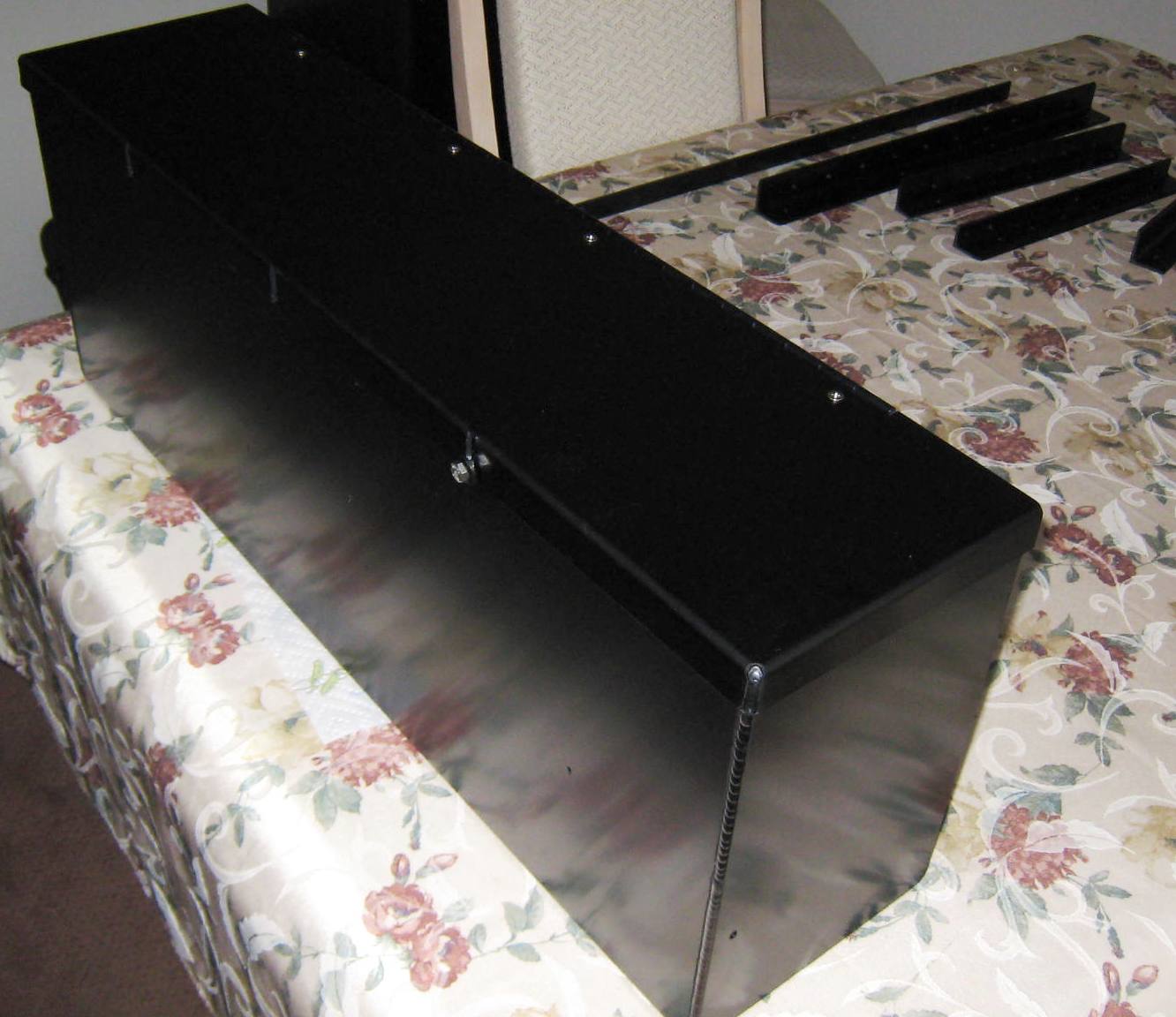
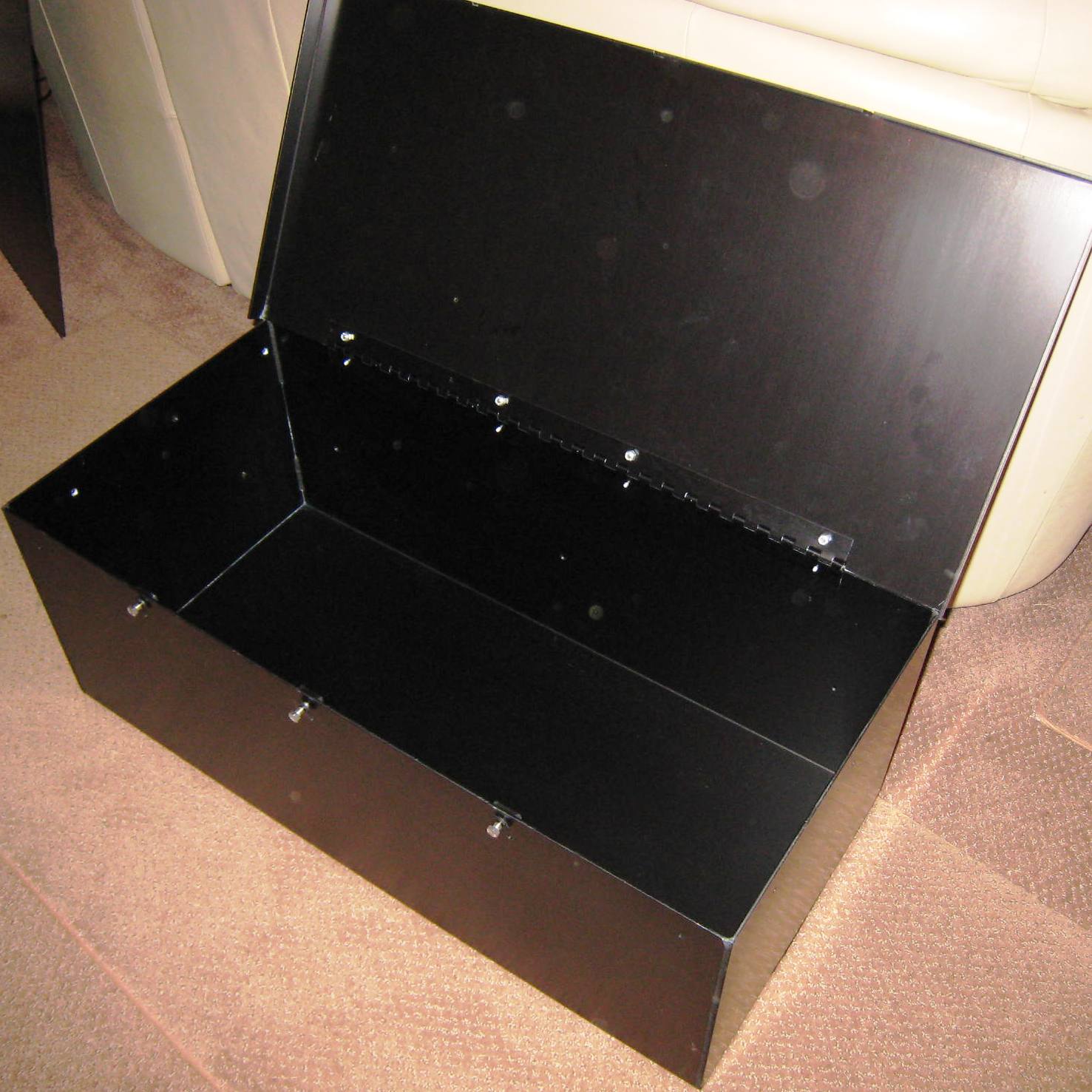
| Accordingly, RCBB is
actually formed of two separate lidded boxes that are bolted together and
additionally joined by pieces of aluminum angle-iron used for mounting
purposes |
||
| Upper 1/3 of RCBB
(with lid closed) |
Lower 2/3s of
RCBB (with lid opened) |
|
|
 |
|
|
----------------------------------------------------------------------------------------------------------------------------------------------------- |
||
|
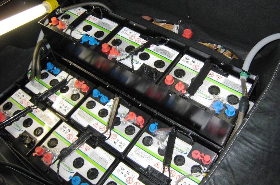
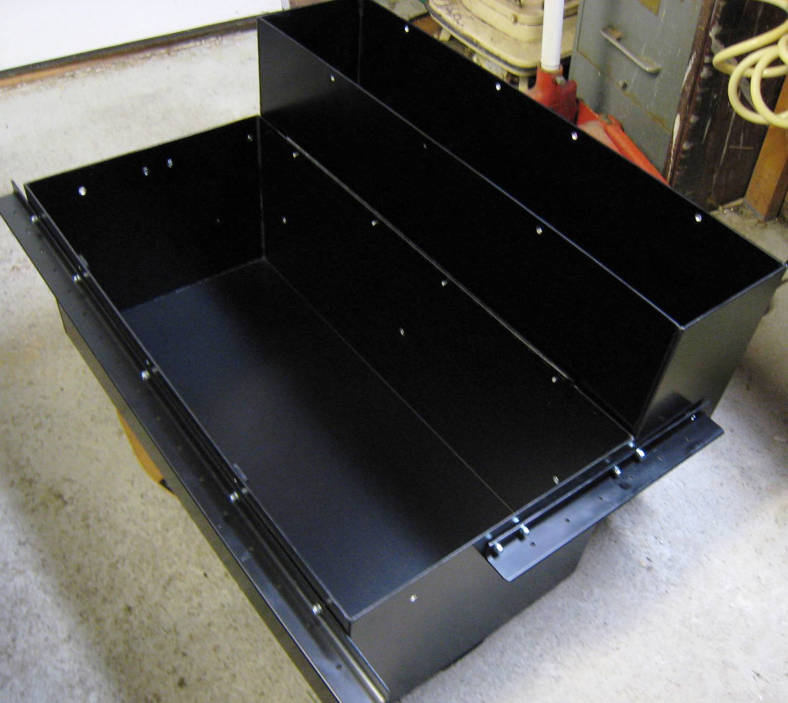
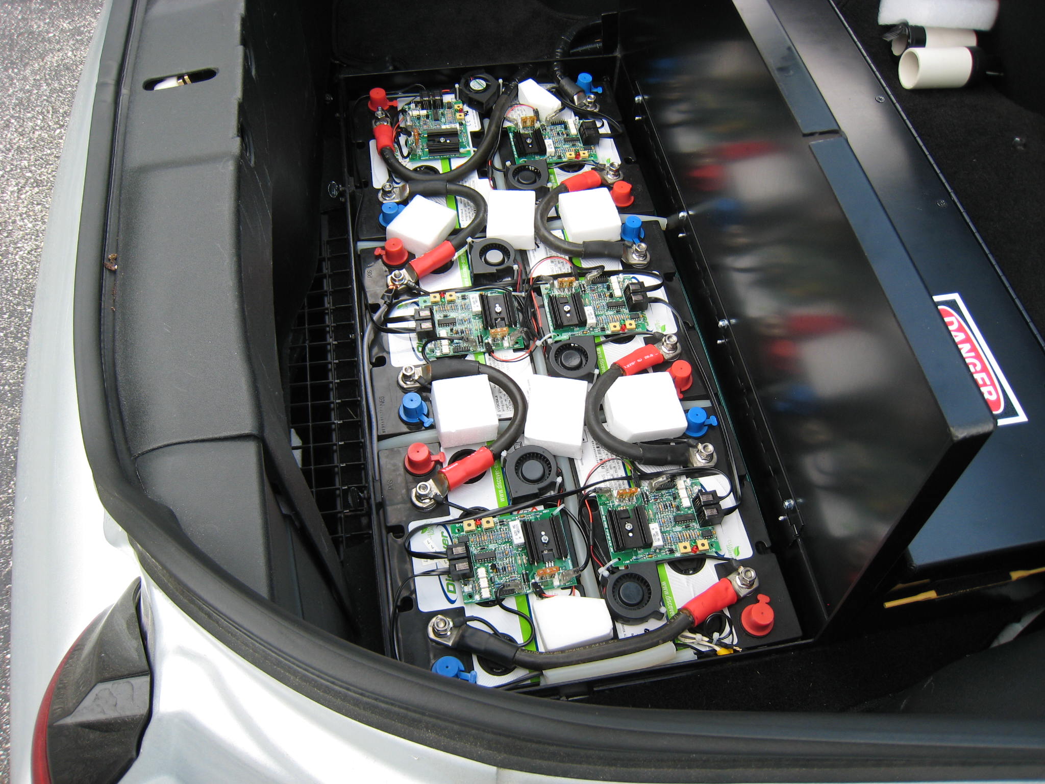
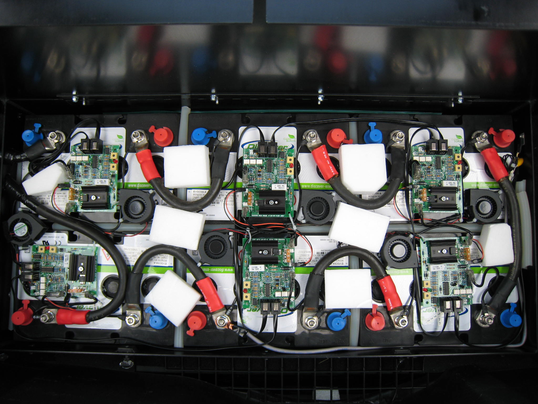
The RCBB shown below, fully assembled with the box lids
removed, and ready for installation. |
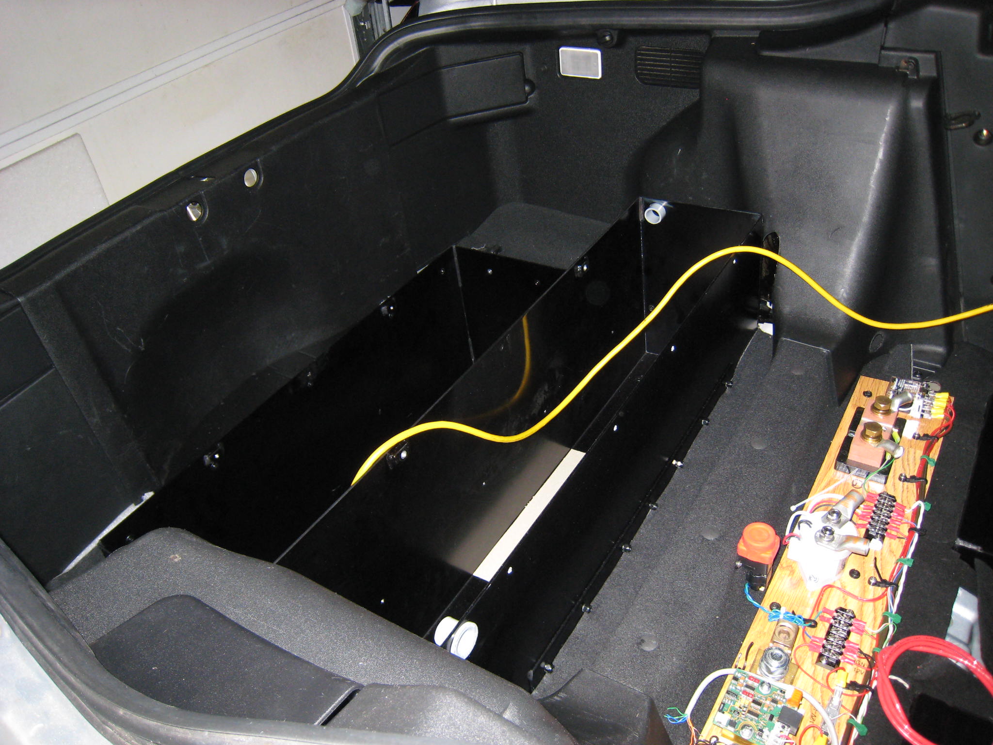
The RCBB is shown below installed,
but empty - as seen looking into the trunk area from a side of the
open rear hatchback. |
|
 |
 |
|
|
--------------------------------------------------------------------------------------------------------------- |
||
| Step-9: High Voltage Wiring (Part I) | ||
| The Cable... | ||
| The high voltage (HV) wiring used
in electric vehicles provides the interconnects that define the "drive
circuit" loop. This is a complete series HV circuit loop that will
typically carry ~500 to ~1000 amps of DC current (for relatively short
intervals). In the case of gas-to-electric conversions, the wire of
choice is welding cable, which is also known as 2/0 gauge wire. It is
about 1/2 thick, and quite stranded for flexibility, as shown in the image to the right. |
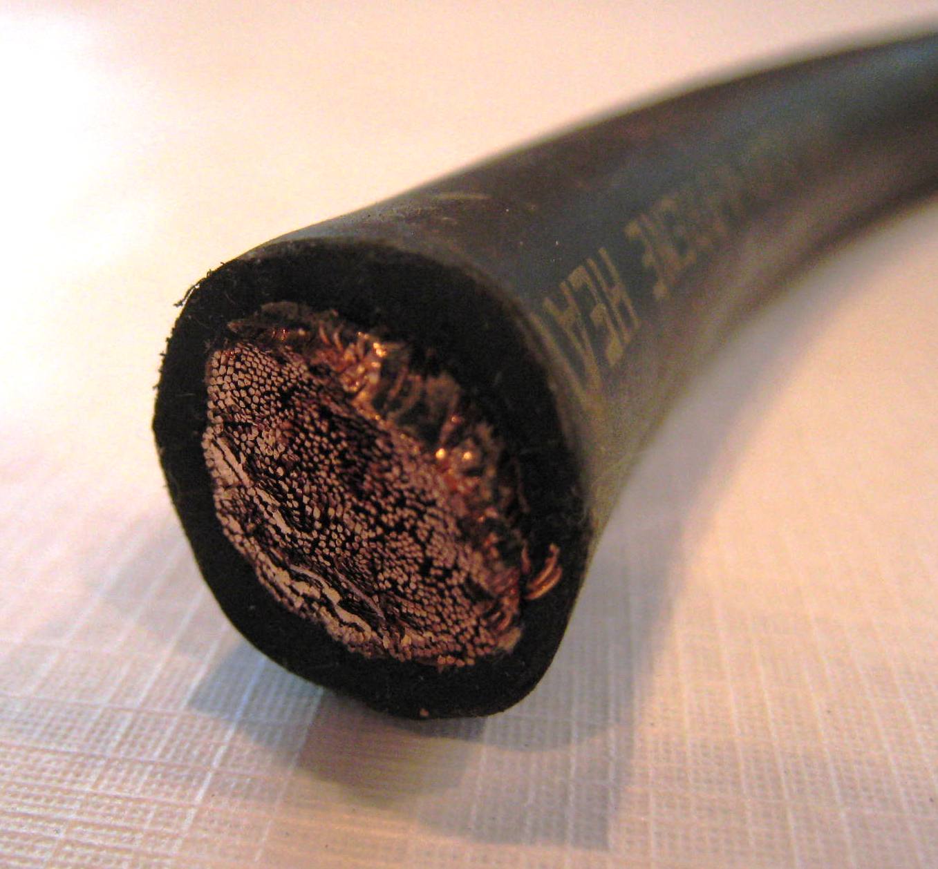 A sample of the 2/0 cable used for HV wiring |
|
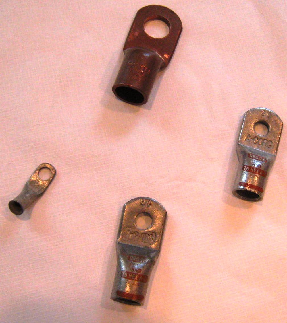 |
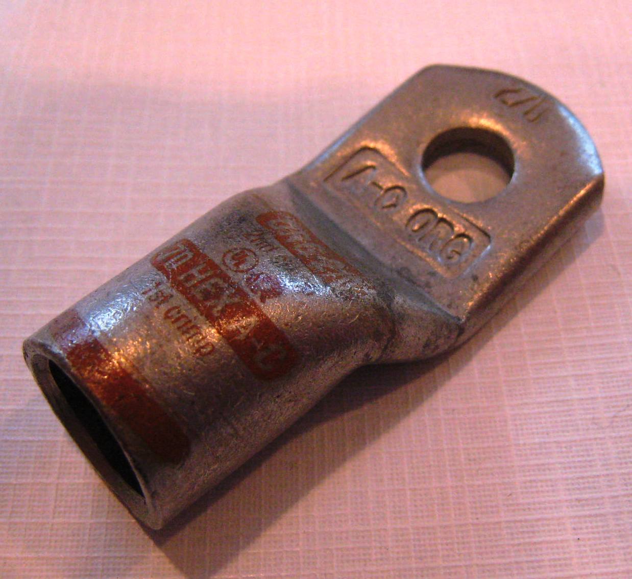
When creating cables for the HV system wiring, crimped end lugs are often used. In the case of the 2/0 lugs, it is best to have available a commercial ratchet-type cutting tool (not shown), along with a heavy duty long-arm crimping tool (see below). | |
| Standard 5/16" end lug Typical crimp lugs | ||
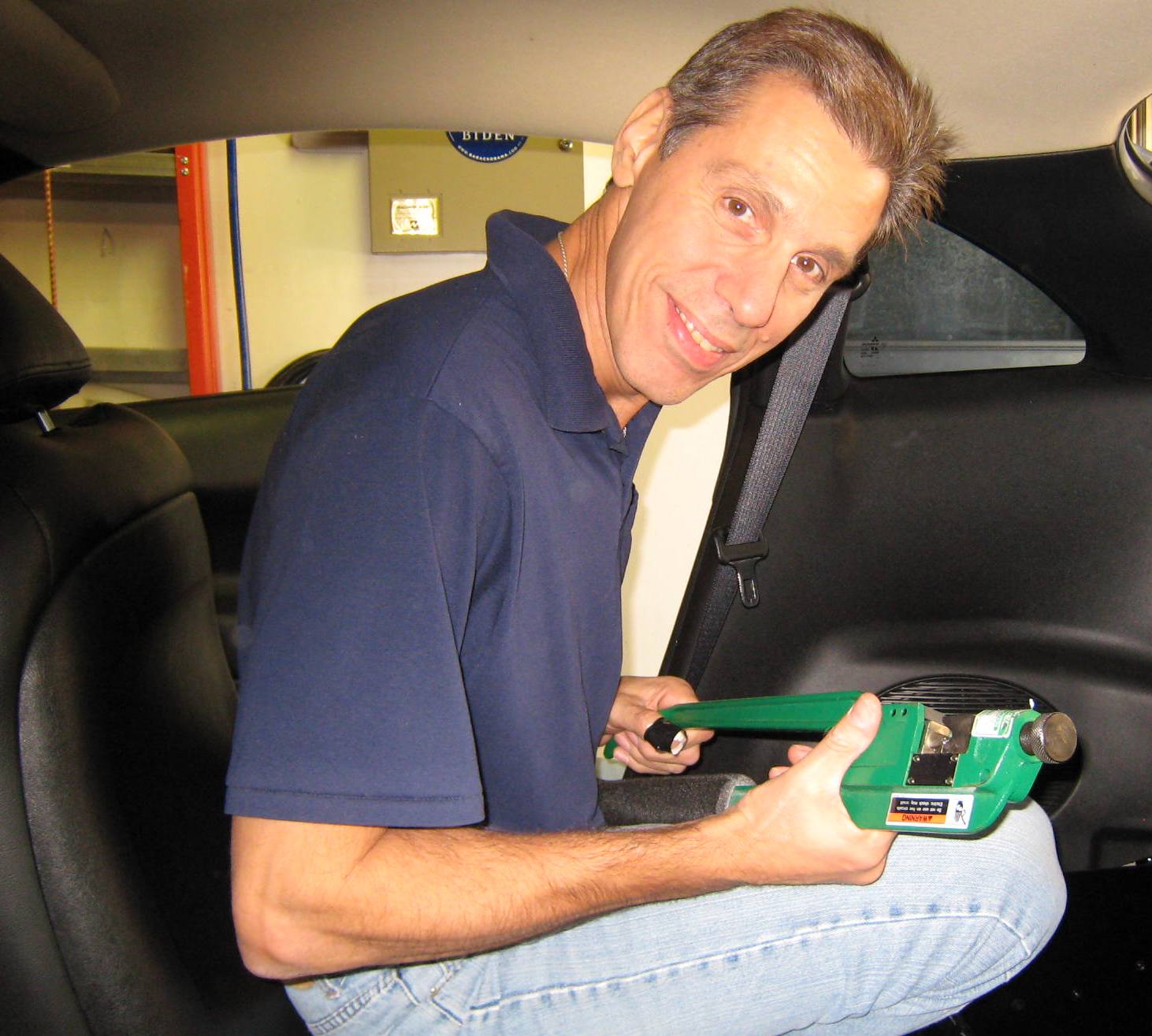
| Shown to the right is Tony Olivo,
who kind of 'volunteered' to crimp some lug ends for me.
Tony has strong arms, which are very helpful when crimping a bunch of 2/0
lug ends. Those that are familiar with such crimping chores will fully understand the amount of strength that each crimp requires... In my case, after 15 to 20 lug end crimps, there was not much left in the tank! Thanks Tony! |
 |
|
|
||
 |
 |
|
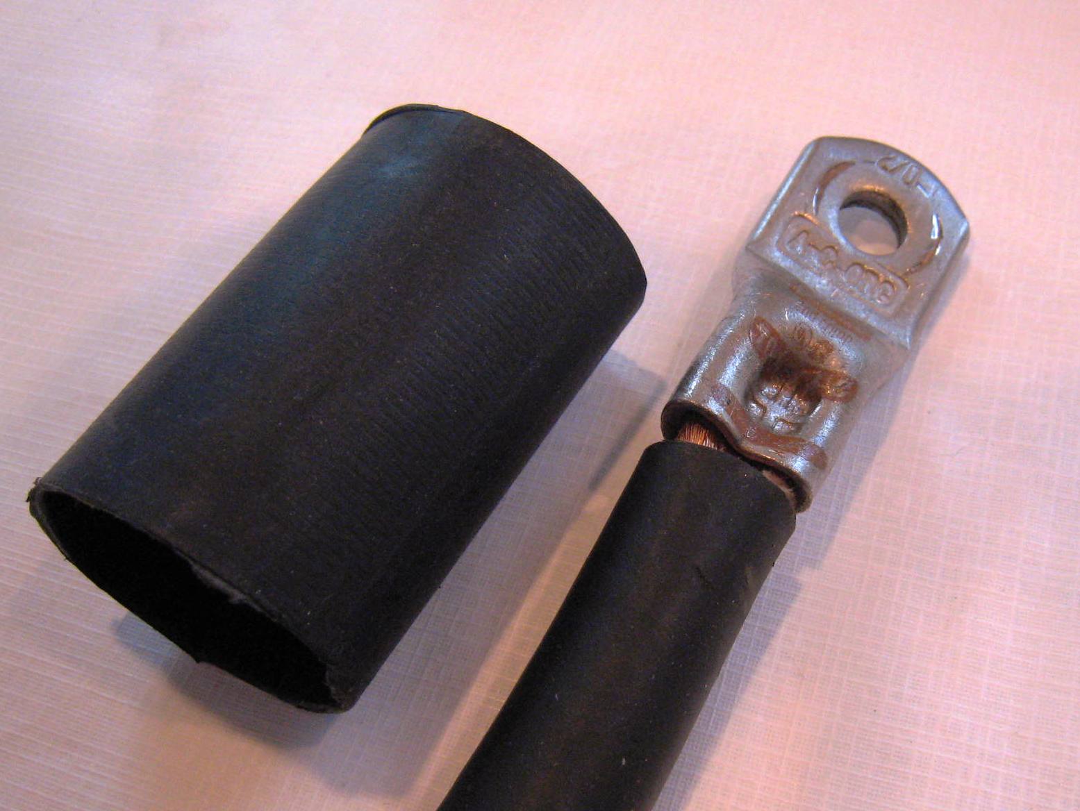
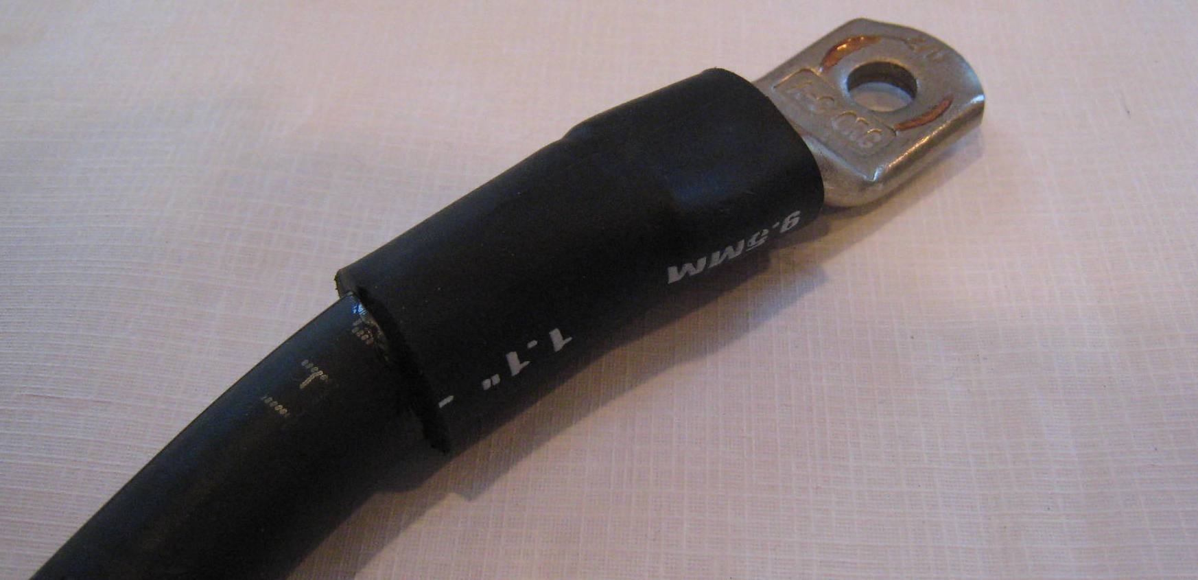
| Single end lug crimped to 2/0 cable |
End after shrink tubing has been applied |
|
 |
||
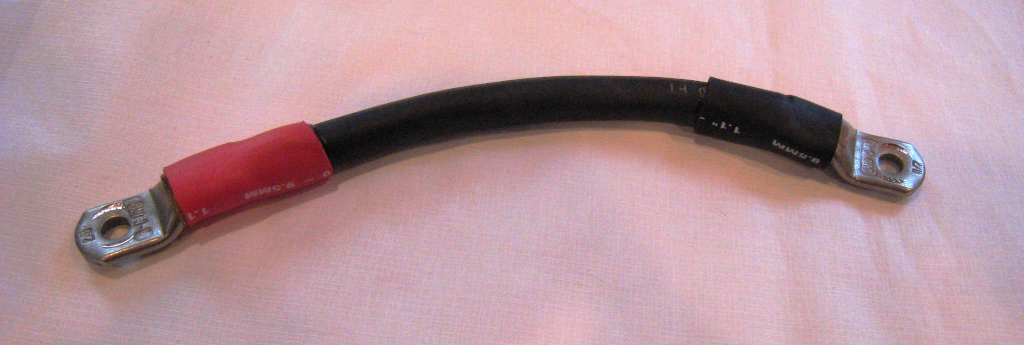
| Typical (and short) HV interconnect cable assembly - note color coded ends. | ||
|
The Battery Box Wiring... |
||
After some consideration, I decided to leave the shrink tubing off for the initial HV wiring - within the battery boxes, as it would make bad (high resistance) connections/crimps easier to see. |
||
 |
|
|
| Mid-car Battery Box - initial test wiring | The HV wiring to the WarP11 motor | |
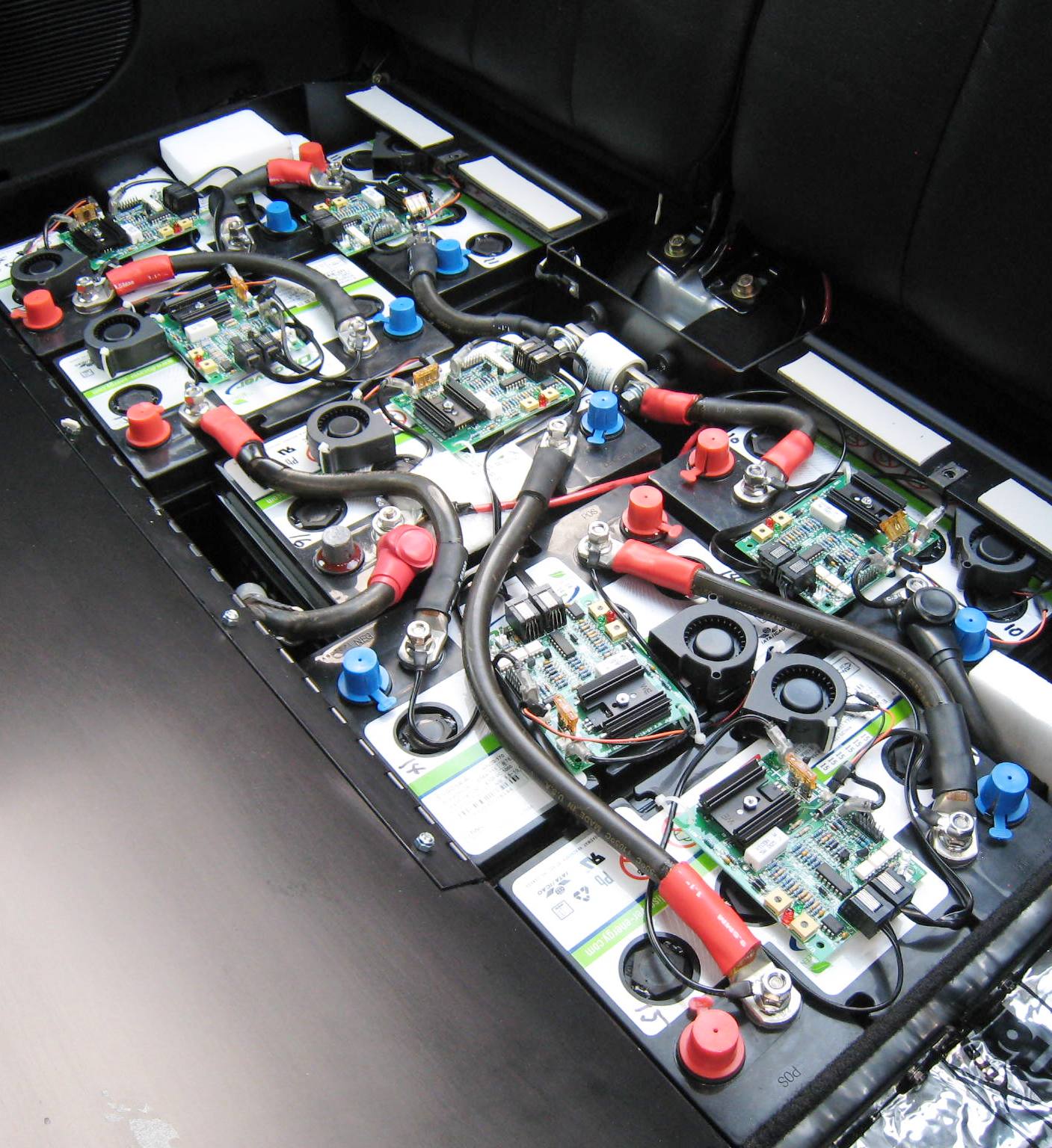
| The mid-car battery box wiring, as shown below partially wired for testing, was a bit more challenging then the rear-car battery box. | ||
 |
The intent with the HV cabling
of each battery box was to eliminate the need to have one HV cable crossing
over a second HV cable.
|
|
| ---------------------------------------------------------------------------------------------------------------------------------------------------- |
||
|
|
 |
|
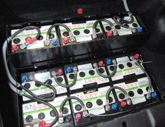
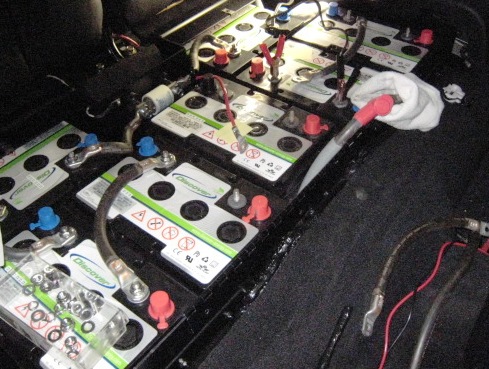
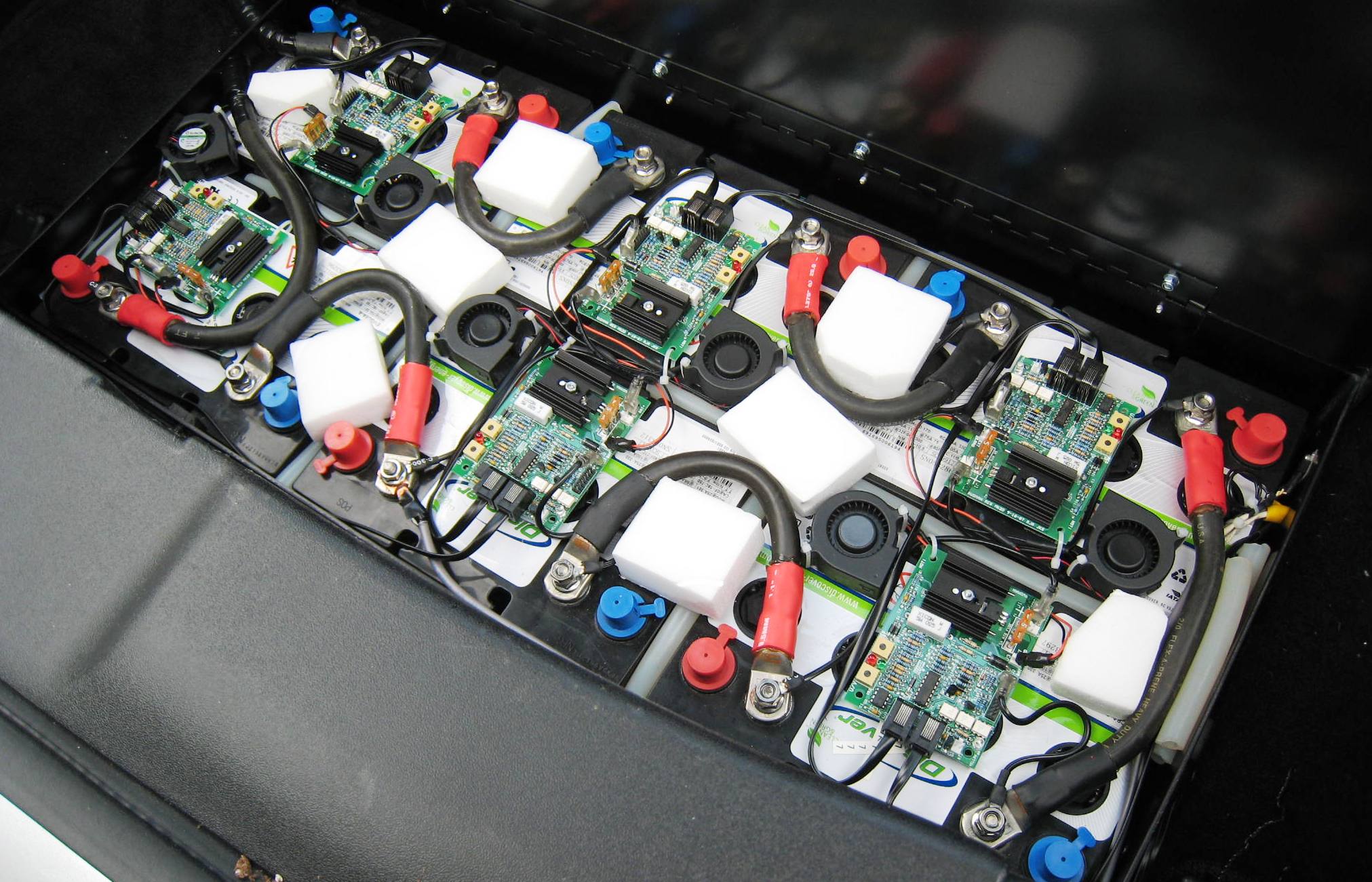
| Final Mid-Car Battery Box | Final Rear-Car Lower Battery Box | |
|
---------------------------------------------------------------------------------------------------------------------------------------------------- Double Insulating HV Cables... |
||
| As an extra safety measure, all HV cabling NOT within another enclosure (e.g., a BB), will be at least double-insulated using an additional sleeve-like material, which is shown below. This outer sleeve or casing is slid over the 2/0 cable using talc powder (a non-drying alternative to soap). | ||
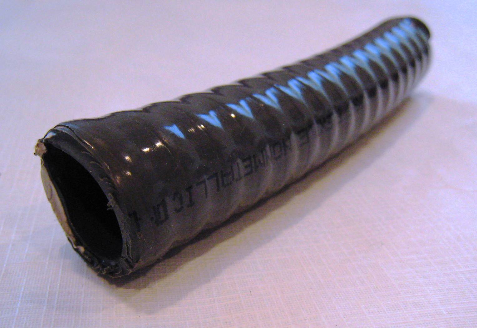 |
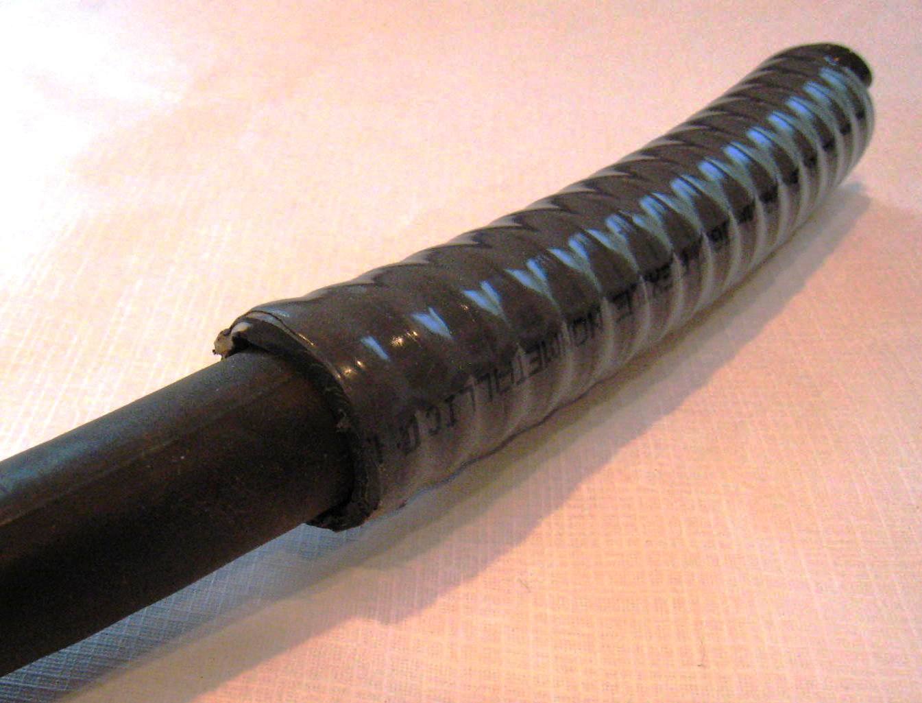 |
| Common casing used in HV wiring to double insulated cable | Standard 2/0 cable is slid inside the sleeving | |
| Some conversionists
run the HV cables from the rear of the car to the front motor compartment
inside the passenger compartment. One good reason to run
the HV cables this way is to provide (usually in the center console) a
manual graspable safety pull-disconnect. This emergency cut-off device is a
last resort, should the DC controller fail full on, and all else fails to
stop the car (e.g., using the ignition key, putting the car in "neutral",
etc.). In deed, in some cases a conversion will remove the clutch (save
weight) and "pin" the transmission in a selected gear (assuming a manual
transmission). It such a case, a safety disconnect is a VERY good idea! In the case of ED-E, should the Raptor controller actually fail full on, and BOTH the front and rear contactors will not open, then there is one other option that is sure to work: the fully functional factory clutch. In fact, some believe a driver is much more likely to depress the clutch pedal before even thinking of reaching down and shutting off the ignition switch. |
||
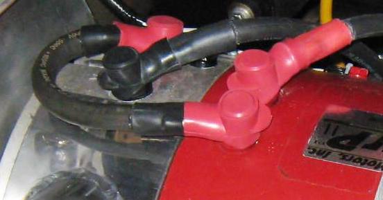
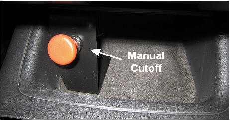
| In adddition, for an extra level of safety, ED-E also includes a manual cable-activated shut off. A cable runs from a pull knob - mounted on the lower center console - into the motor compartment. This cable enables the driver or passenger to manually open a pair of 250A circuit breakers, which are discussed below when referring to the HV controller (plate) assembly. | ||
 |
||
| Bright red manual cutoff pull knob | ||
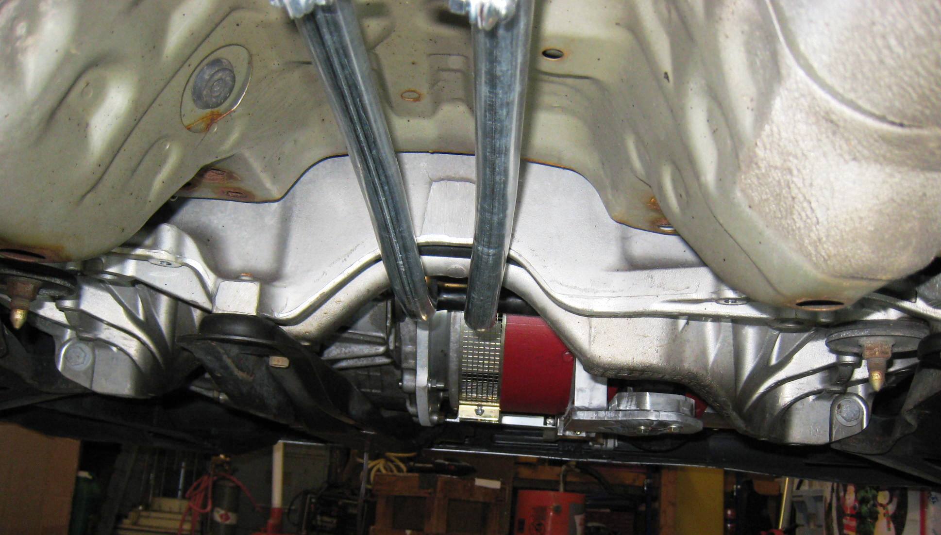
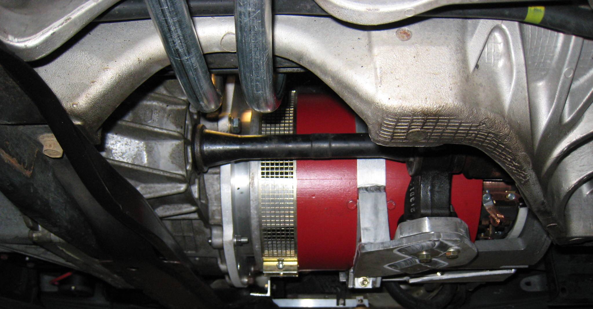
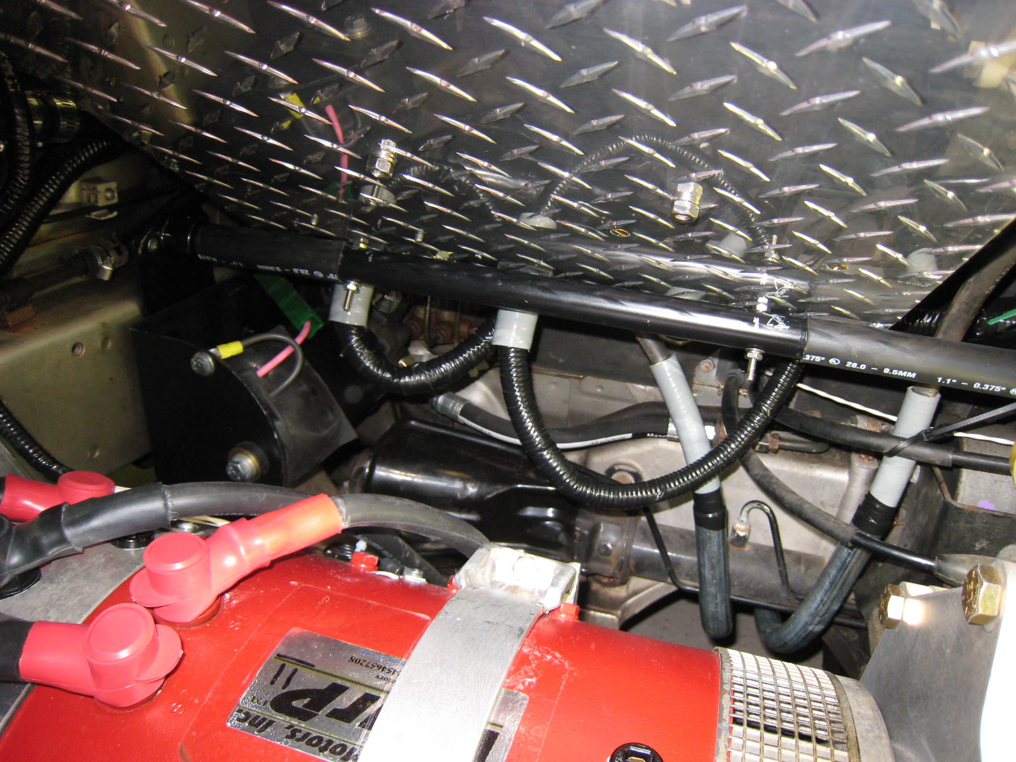
| The use of a remotely activated manual cutoff was employed so that the main HV positive cable and the main HV negative cable would be routed under the car and down the center hump, where the main exhaust tube was originally located. It was also decided that in addition to placing the above discussed outer sleeving over these main HV cables, an outer electrical conduit made of metal would also be used... As clearly shown below. | ||
 |
 |
|
| Under ED-E, looking forward... Two main HV cables Close-up view of the main HV cables and WarP11 motor | ||
 |
 |
|
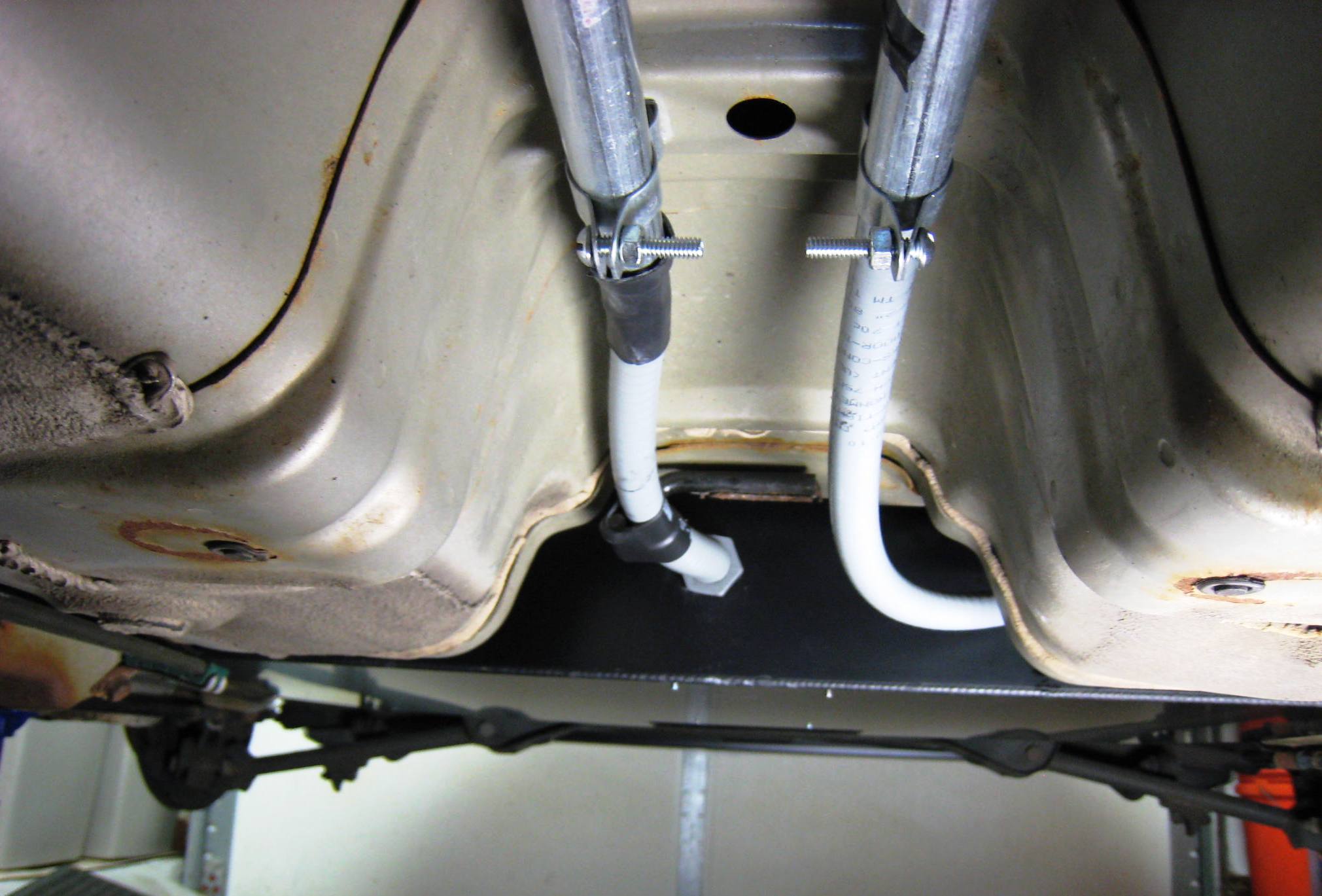
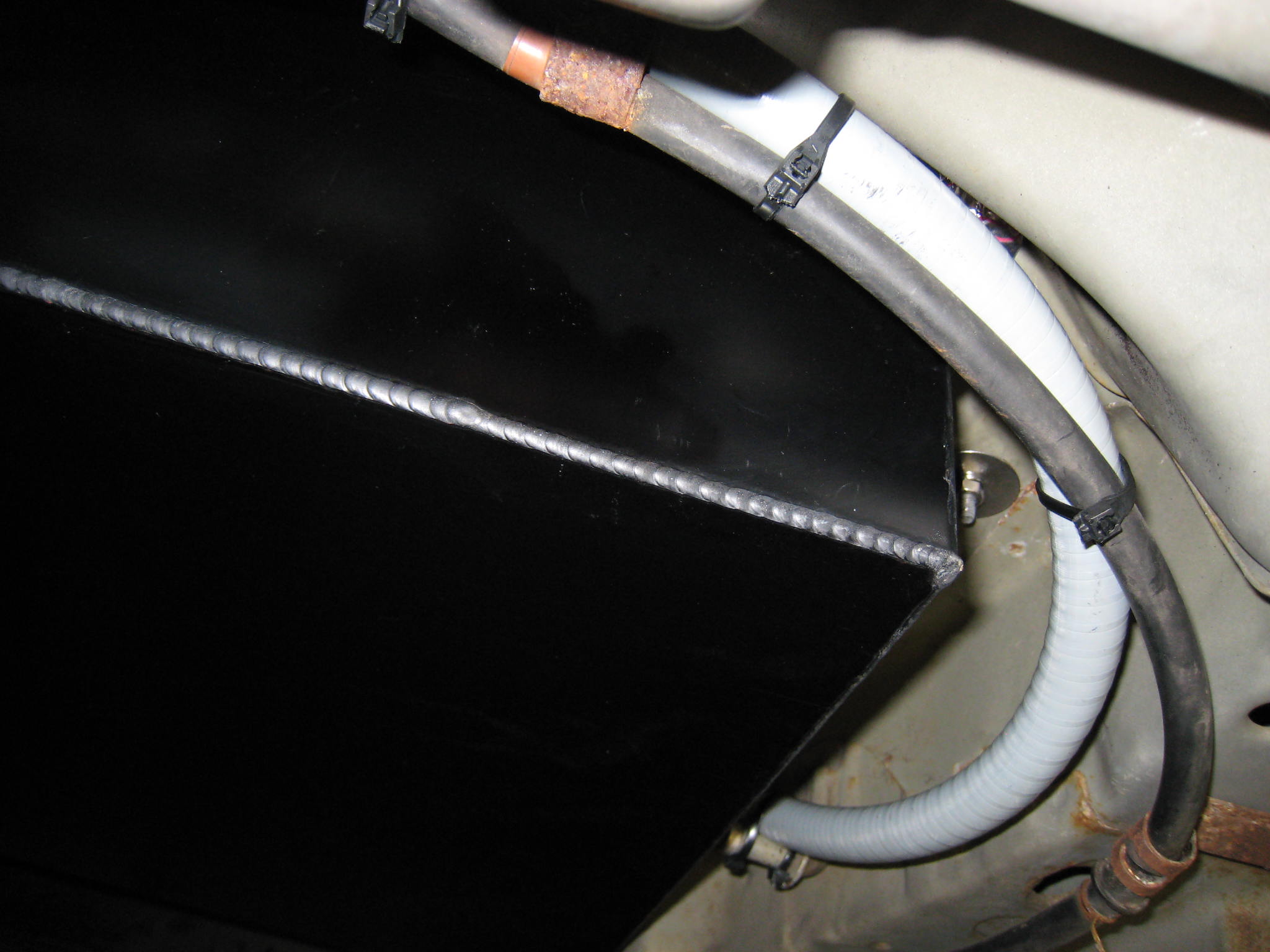
| Looking back... Note the HV (+) cable on the left HV (-) cable coming from Rear HV Contactor Board | ||
| In addition to making sure the under-car HV cables are well secured and up quite high, as can be seen in the above and below pictures, the battery box bottoms are as low as possible, yet still above the frame and axle structures. Meaning lowest possible center-of-gravity, with maximum possible ground clearance. | ||
 |
||
| Step-10: High Voltage Wiring (Part II) | |||
| The Rear HV Contactor Assembly... | |||
|
|
|||
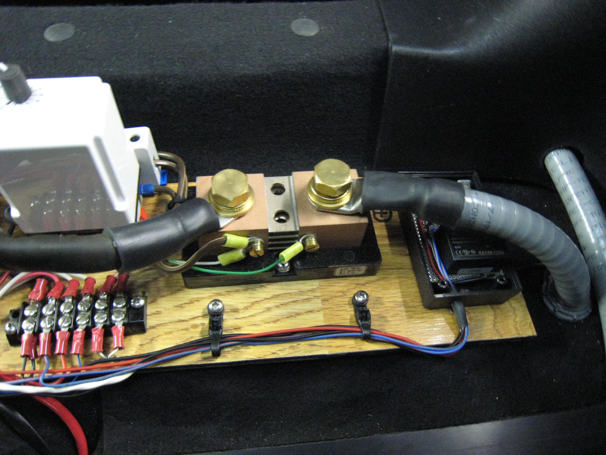
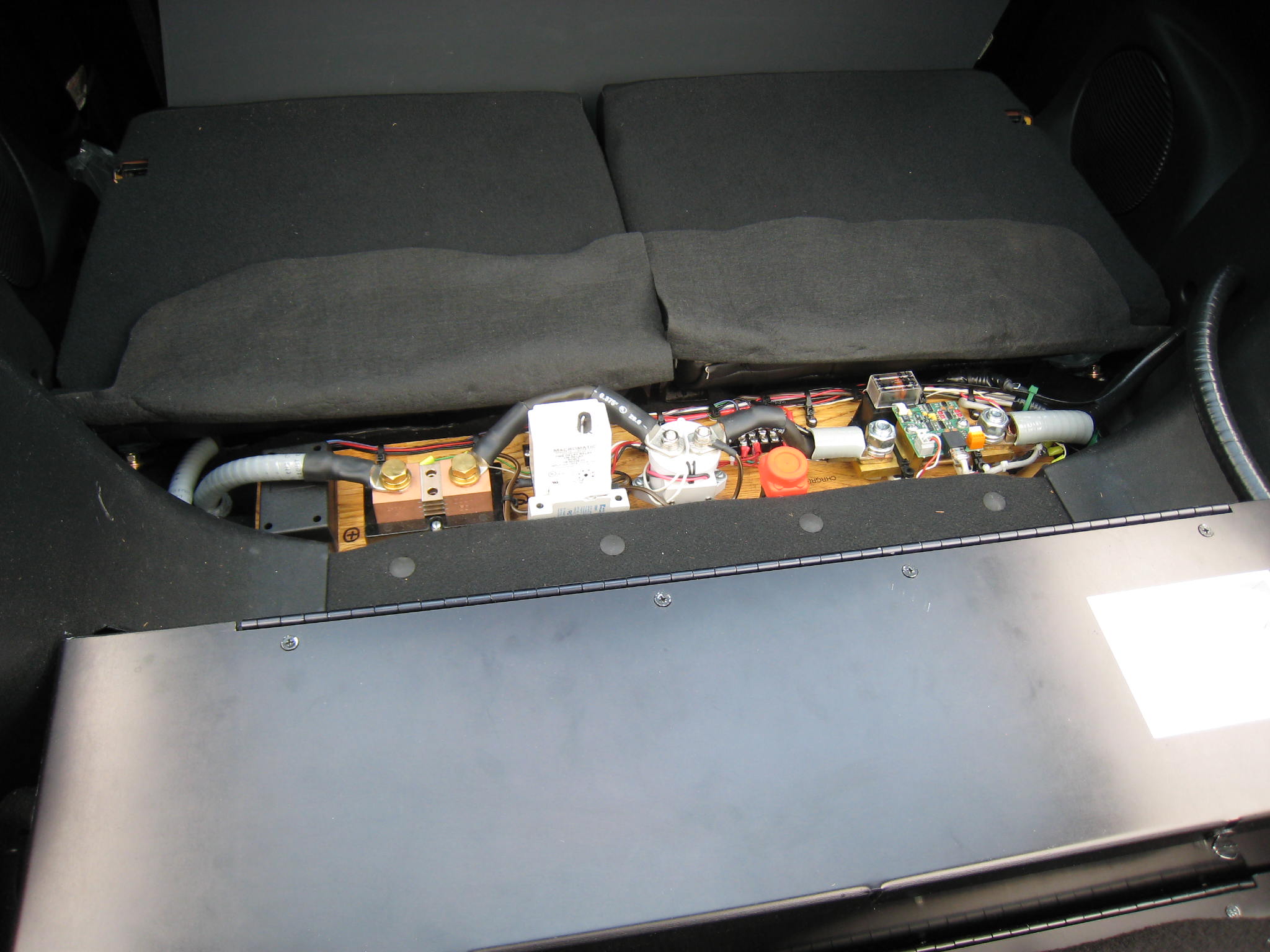
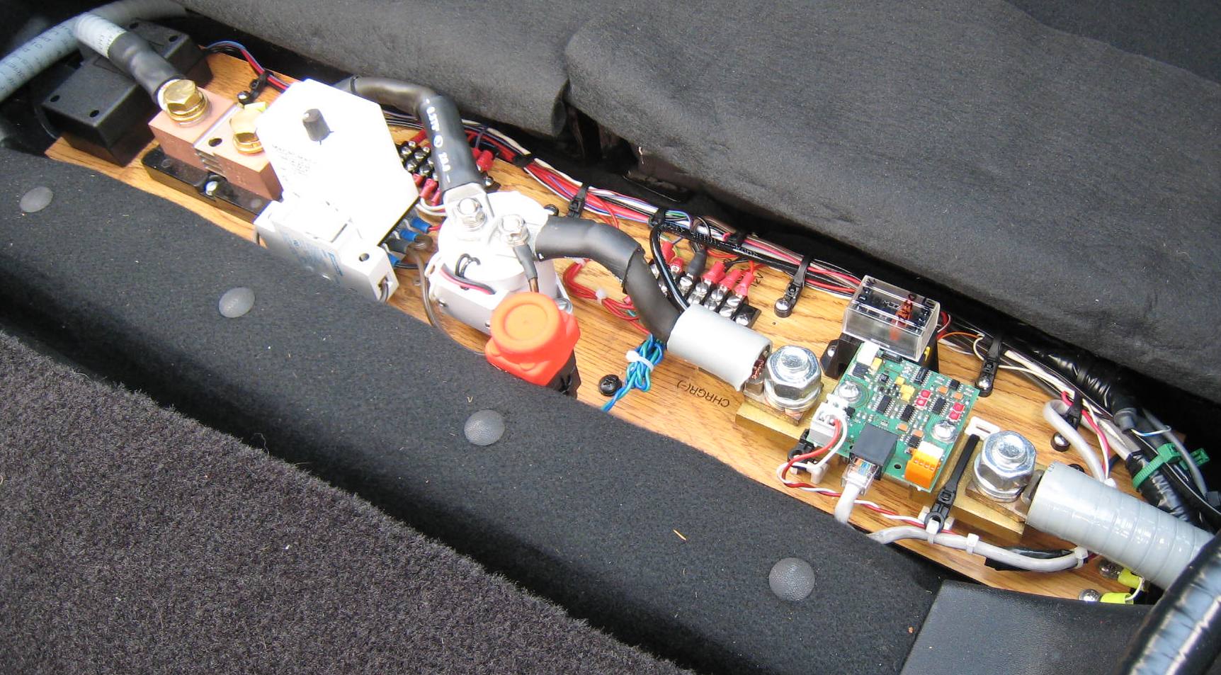
 |
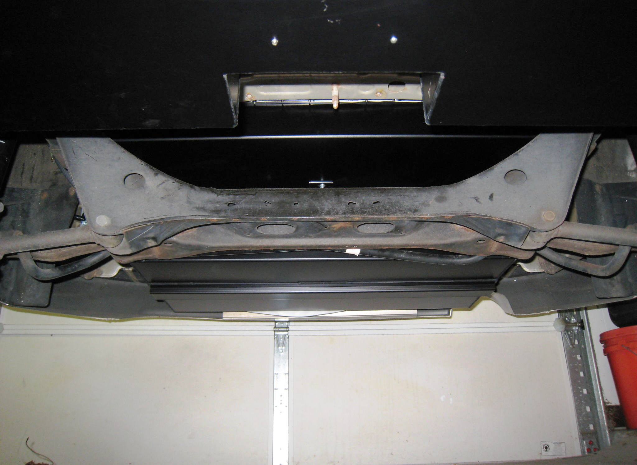
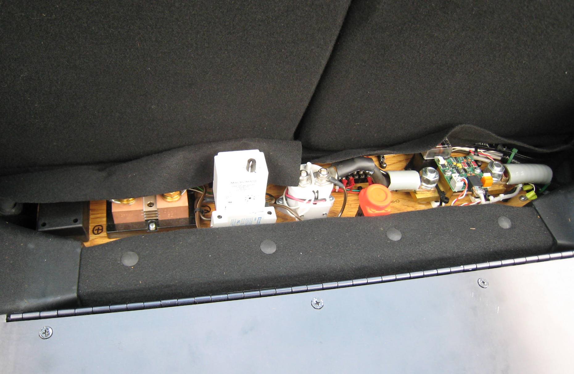
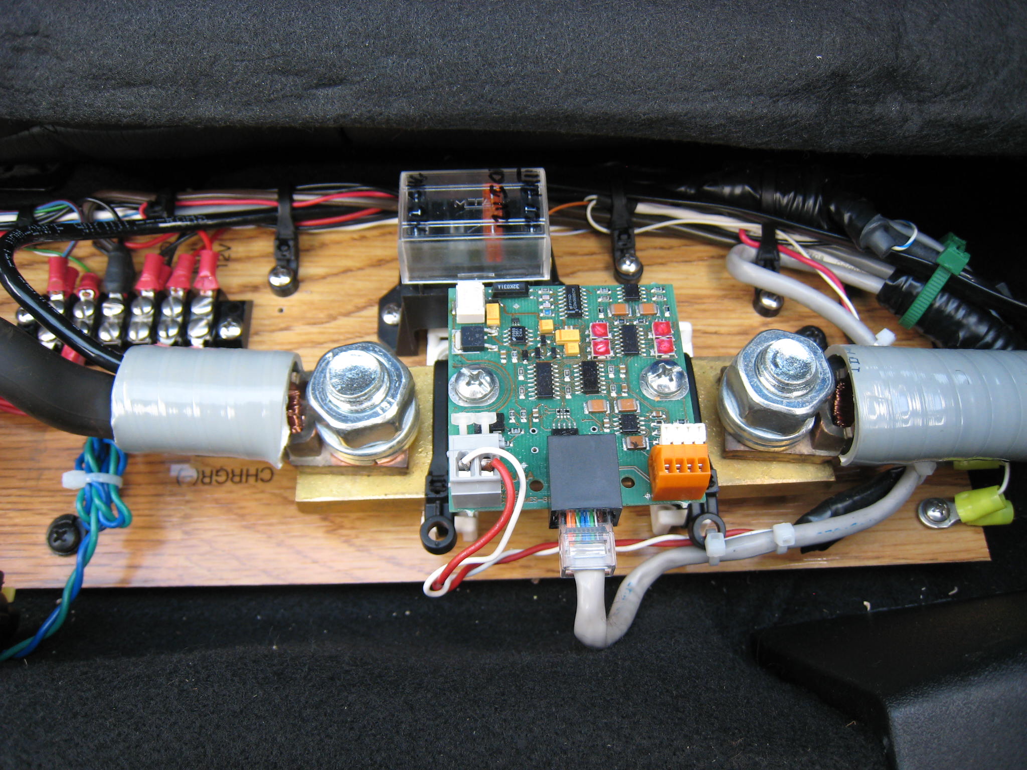
The rear HV contactor assembly will house a number of important components. These include the 1000A shunt for the in-dash analog current meter, the rear-car contactor (shown on the left of the image to the left), and the EVision system 500A shunt (right side of image). | ||
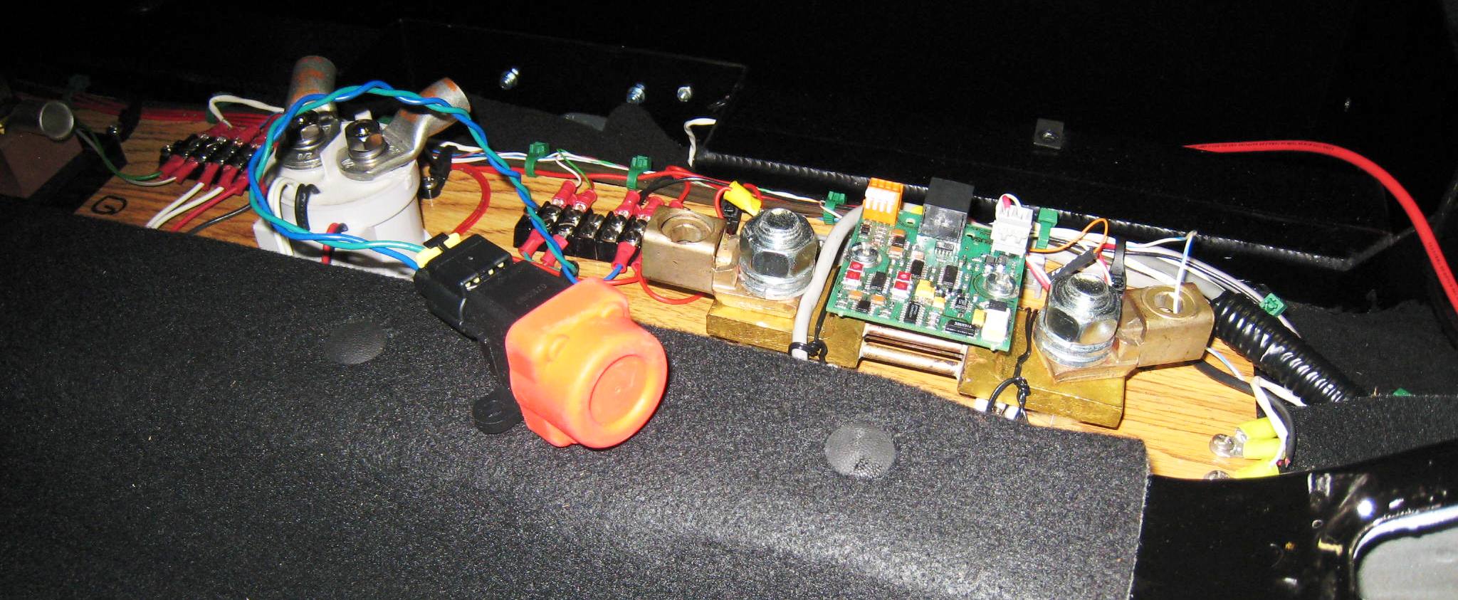
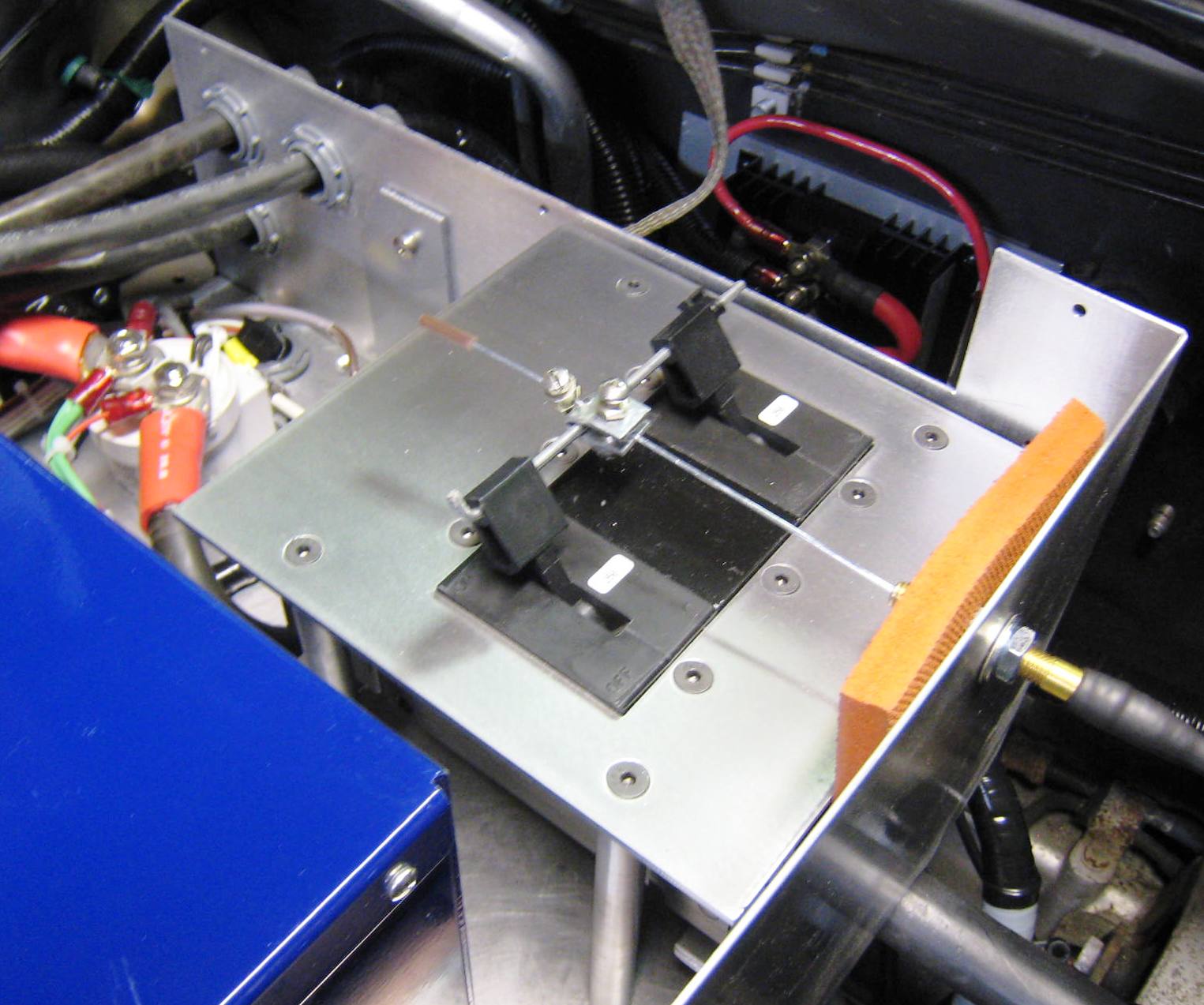
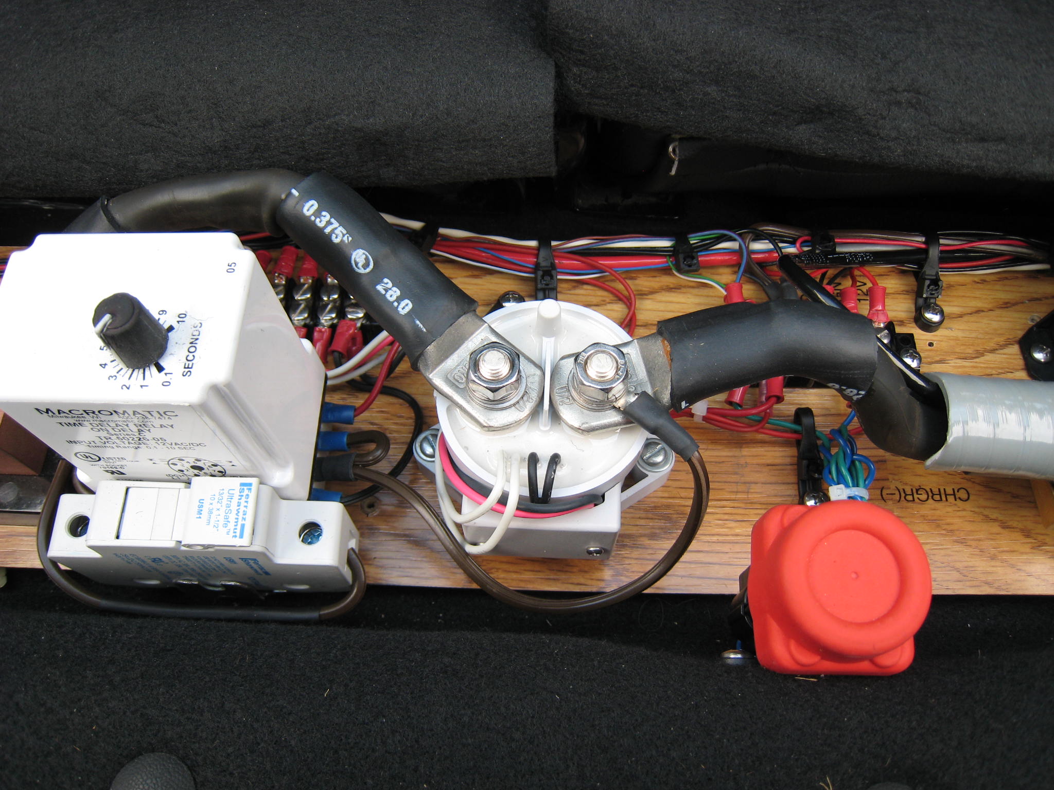
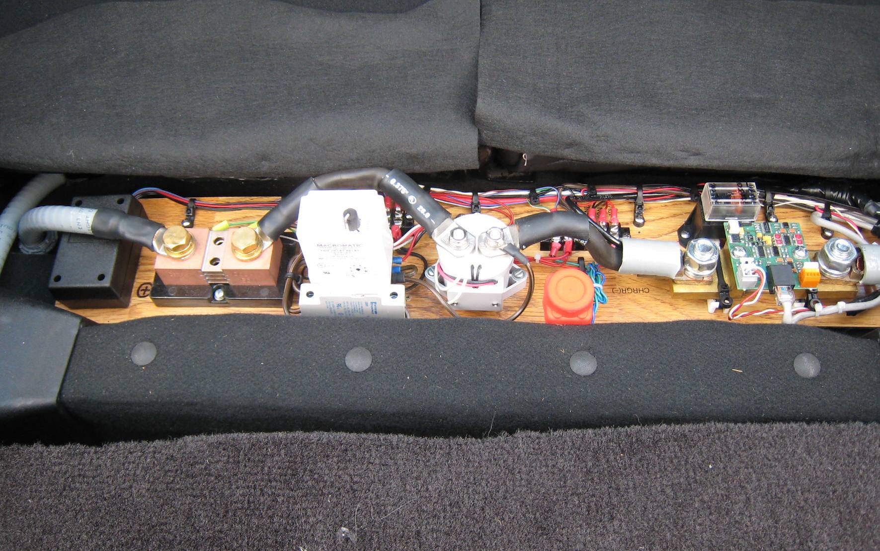
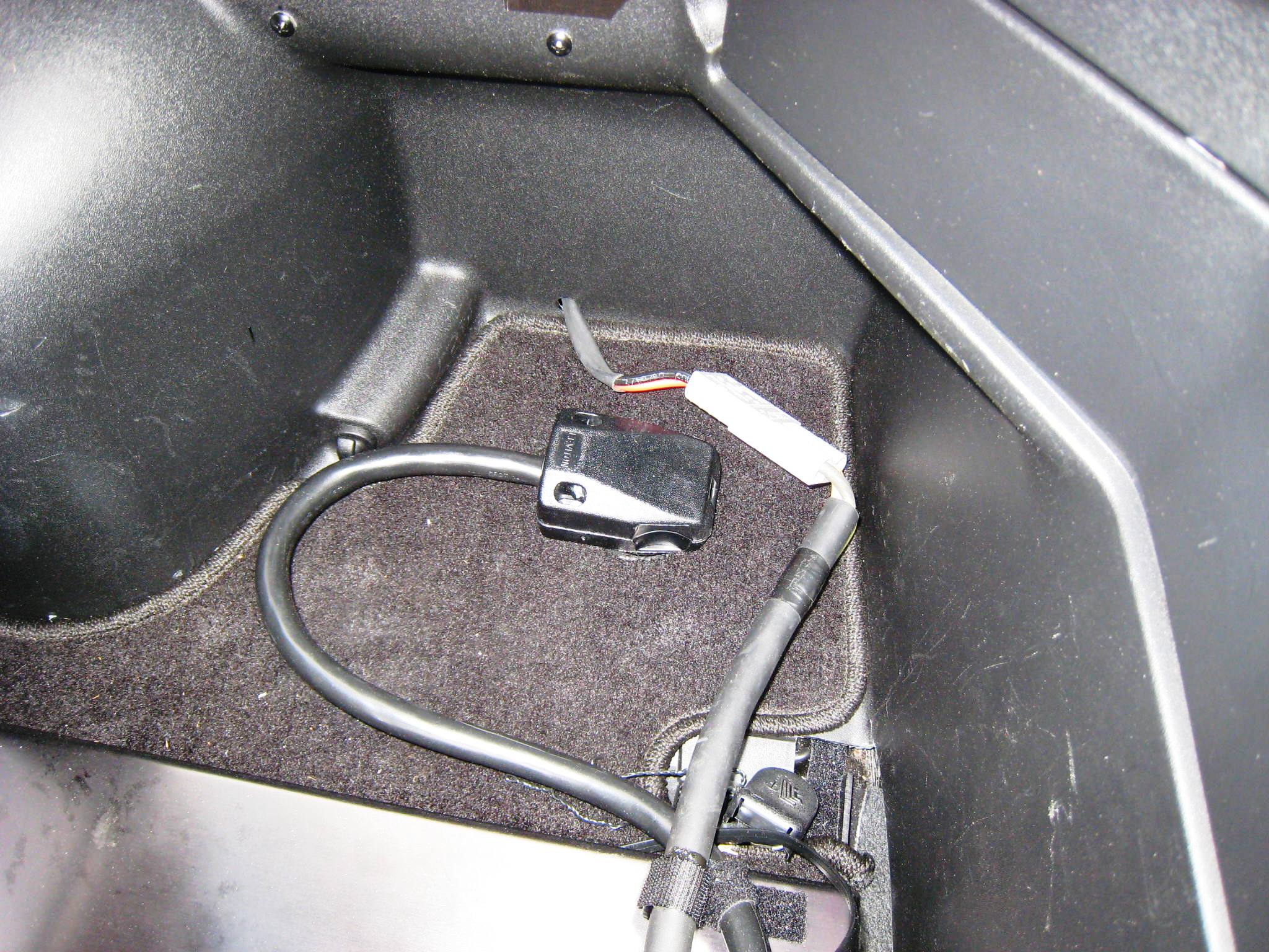
| A red topped inertia cutoff switch, shown below before mounting and to the right after mounting, is a safety device that is strongly recommended. The idea is that if your vehicle is in a collision, the switch will (in theory) cutoff the traction pack high voltage, and kill the motor. |
 |
||
|
|
|
||
|
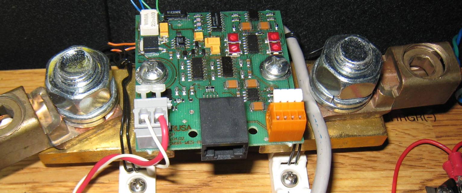
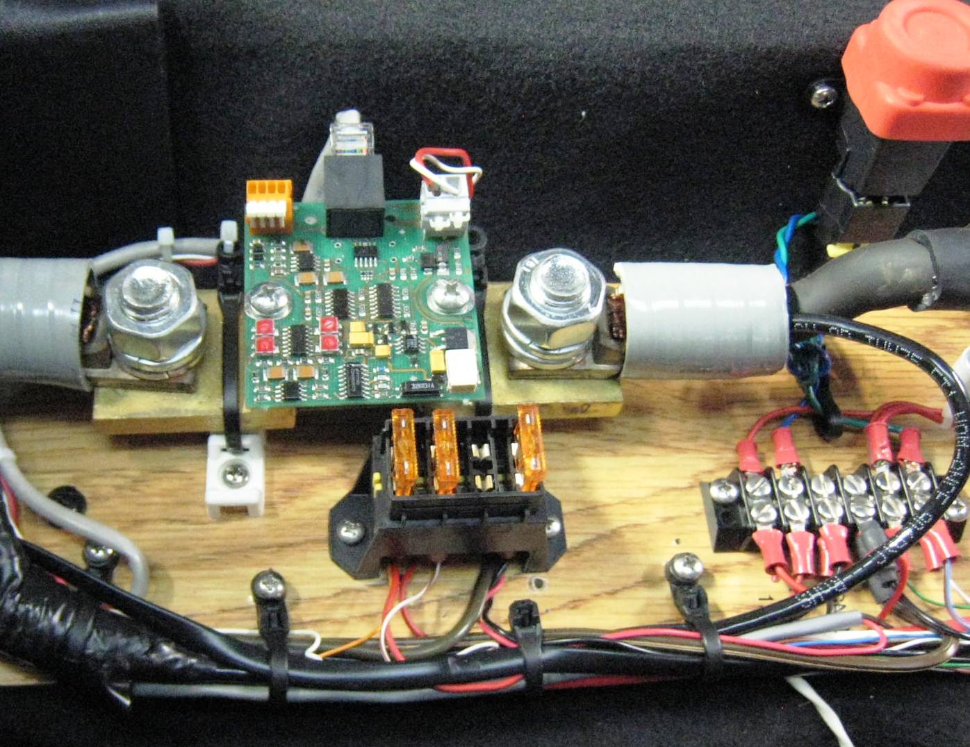
To the right is a close-up view of the EVision 500A shunt PCB. This is
one of several EVision modules that are interconnected by a dedicated CAN
bus. The black can bus connector can be seen in the middle lower
portion of the image to the left. |
 |
||||
|
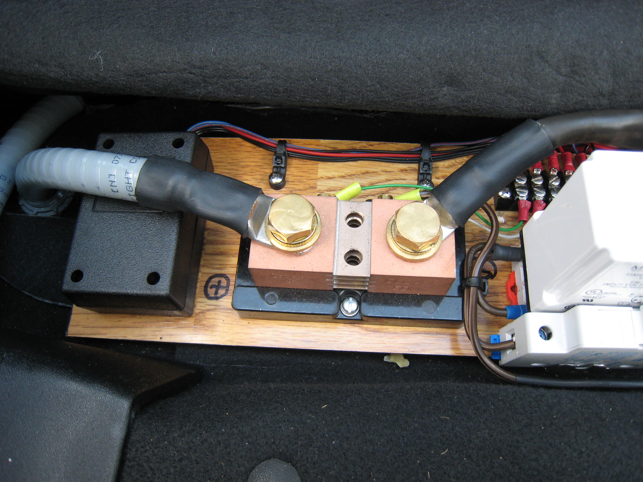
The right side end of the rear HV contactor assembly. Shown
in the center is the 1000A in-dash current meter shunt. The white
time-delay relay (shown on the left) and a fuse (behind the white time-delay
relay)
were added to enable the DC-DC converter to charge the 12V accessory battery
when the traction pack is being charged.
|
 |
||||
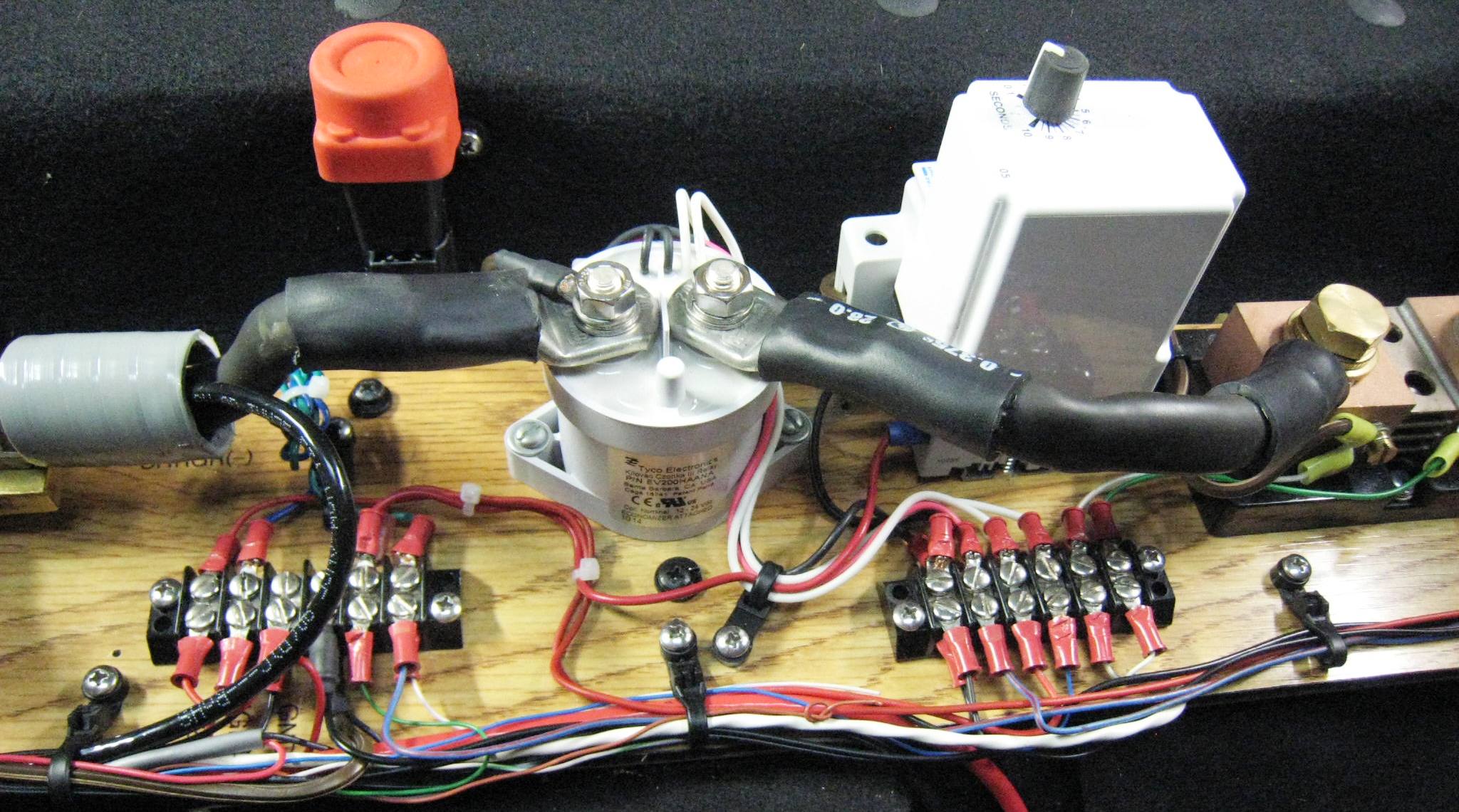 |
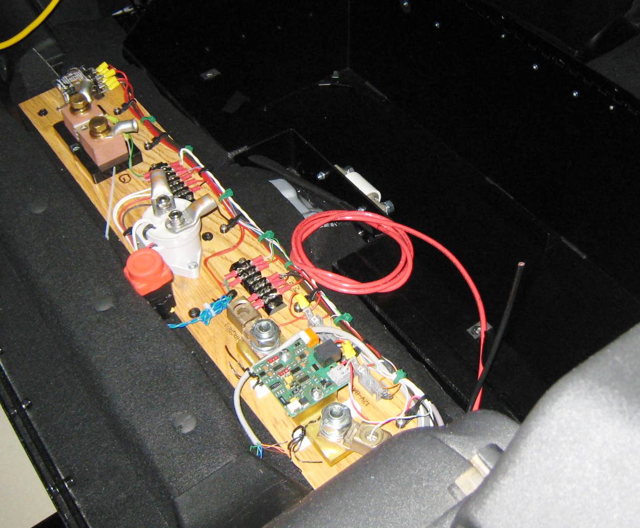
The center portion of the rear HV contactor assembly with the
time-delay relay and rear contactor fully wired. Note the use of terminal
blocks for interconnects and junctions.
|
||||
|
The left side of the rear HV contactor assembly, again
showing the EVision shunt PCB board. Note the CAN bus cable and
connector end, along with several added blade fuses, which can be seen in
the image to the right, just below
the EVision shunt PCB.
|
 |
||||
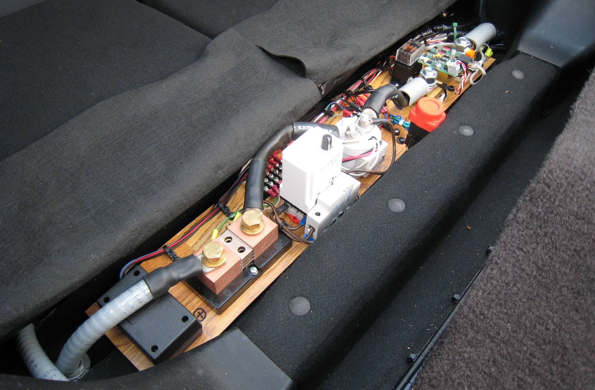 Finished/Updated Rear HV Contactor Assembly
|
|||||
| 11 Front HV Controller Plate/Box | |
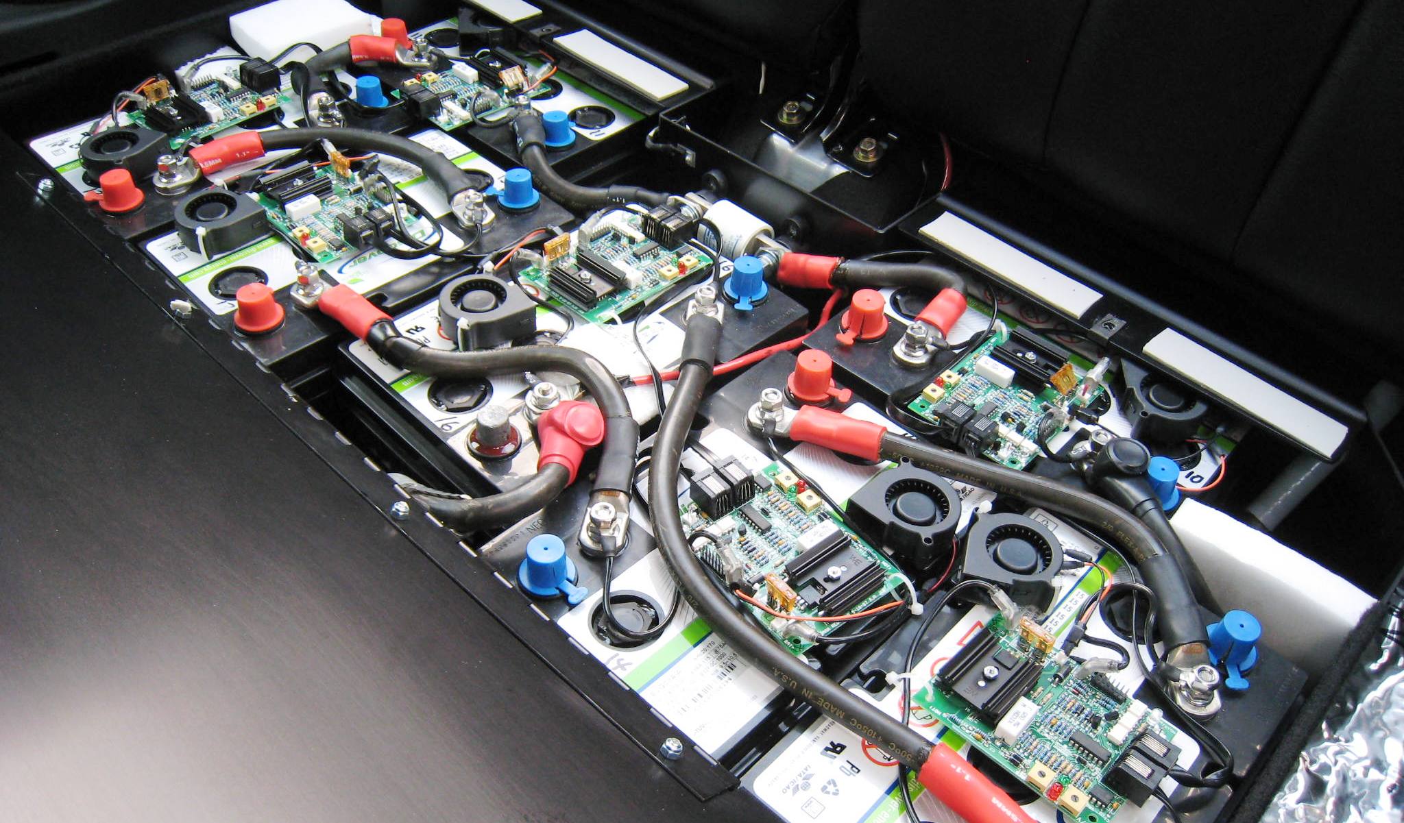
| Often a number of
important items must be mounted up-front in the motor compartment, and close
to the motor. For example, typical items include the DC controller, a
HV contactor, fuses, circuit breakers, solid state relays, ... Just to list a few. In
addition, many many conversionists employ a wooden or metal plate to mount
and secure these items. Several examples located on the Internet are
shown below... |
|
|
|
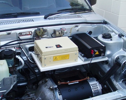 HV Plate (white) with a separate component box (on lft) |
|
|
|
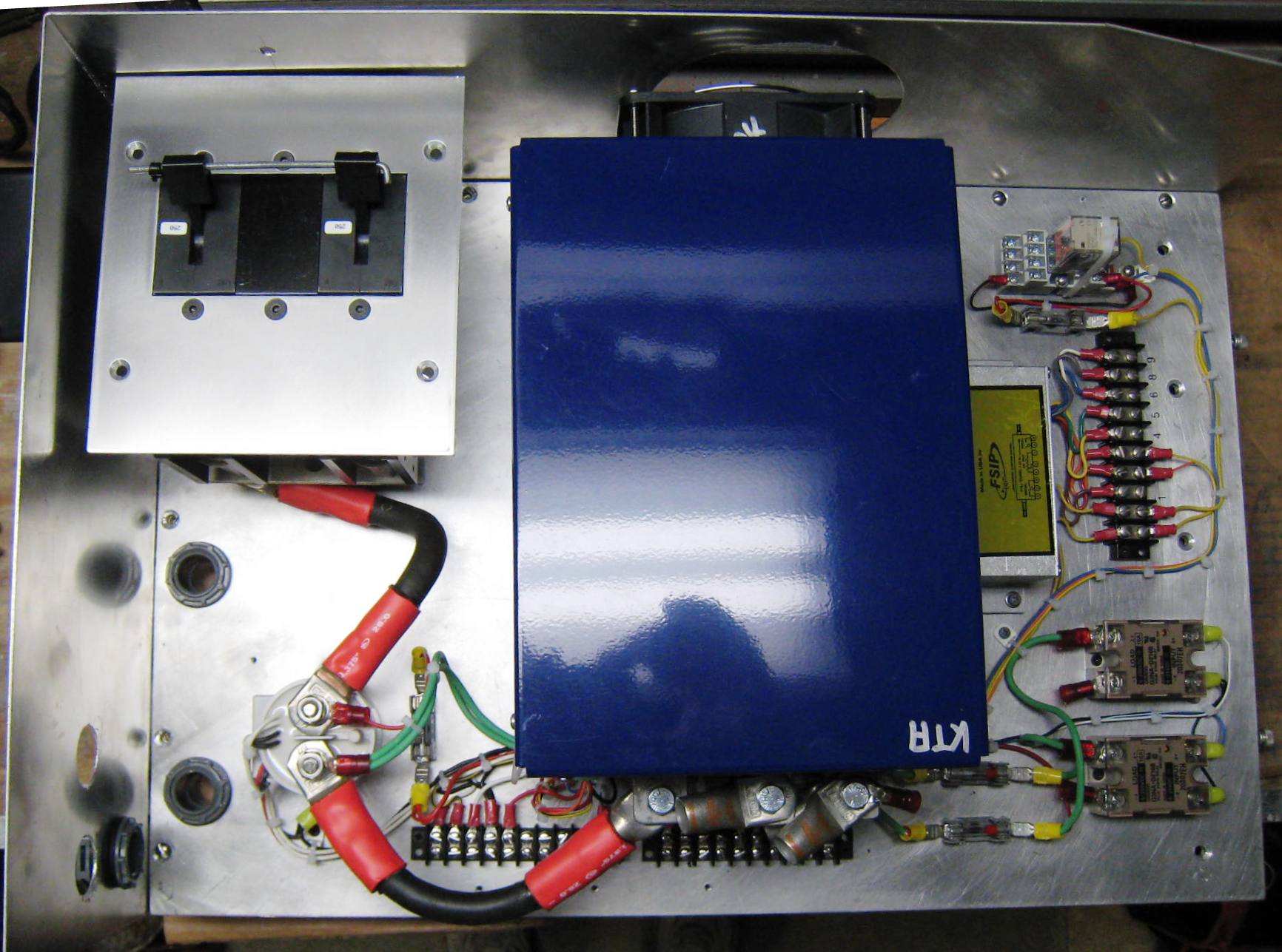
In the case of ED-E, there were several goals for the front HV assembly. First, it had to provide a substantially water resistant housing for the Raptor 1200 controller, which is air-cooled and not fond of water. Second, the front HV contactor and a pair of paralleled 250A circuit breakers must be mounted as close as possible to the Raptor 1200, and ultimately close to the motor. In addition, the plate/assembly must 'lift' to provide access to the motor - without any wires having to be disconnected. |
|
| After evaluating several possible layouts, and making a full scale prototype using heavy cardboard, an optimal organization having very short HV cable interconnects was found. This final layout also provided relatively good access for any needed future repairs and service. | |
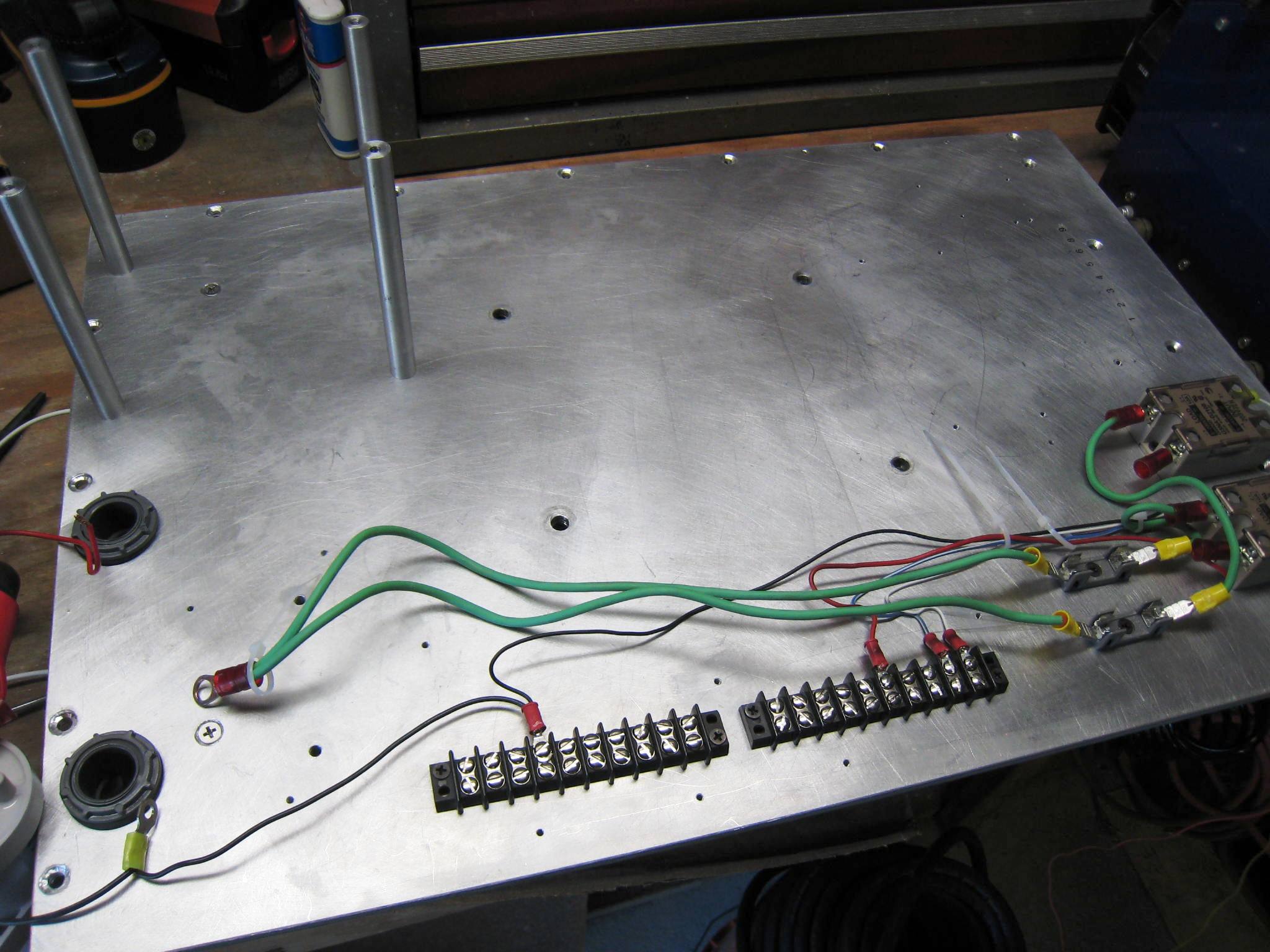 1/4" Aluminum base plate for front HV assembly |
A 1/4" slab of aluminum was purchased at a nice discount because
the piece was almost the exact size needed, but had diamond plating on the
bottom side (which did not matter is my case). The plate is shown on the left, early is the fabrication process. At this point many holes have been drilled and tapped, and a few components mounted.
|
||||
| Next the paired
circuit-breakers were mounted (upper left), and wired to the front contactor
(lower right). This contactor will ultimately be controlled by the Raptor
1200 (which is to be mounted using the largest holes, located near the
center of the plate). A special thanks to Lester Orlik, a very competent machinist and mechanical designer for helping with several mechanical pieces used on the front HV Assembly. |
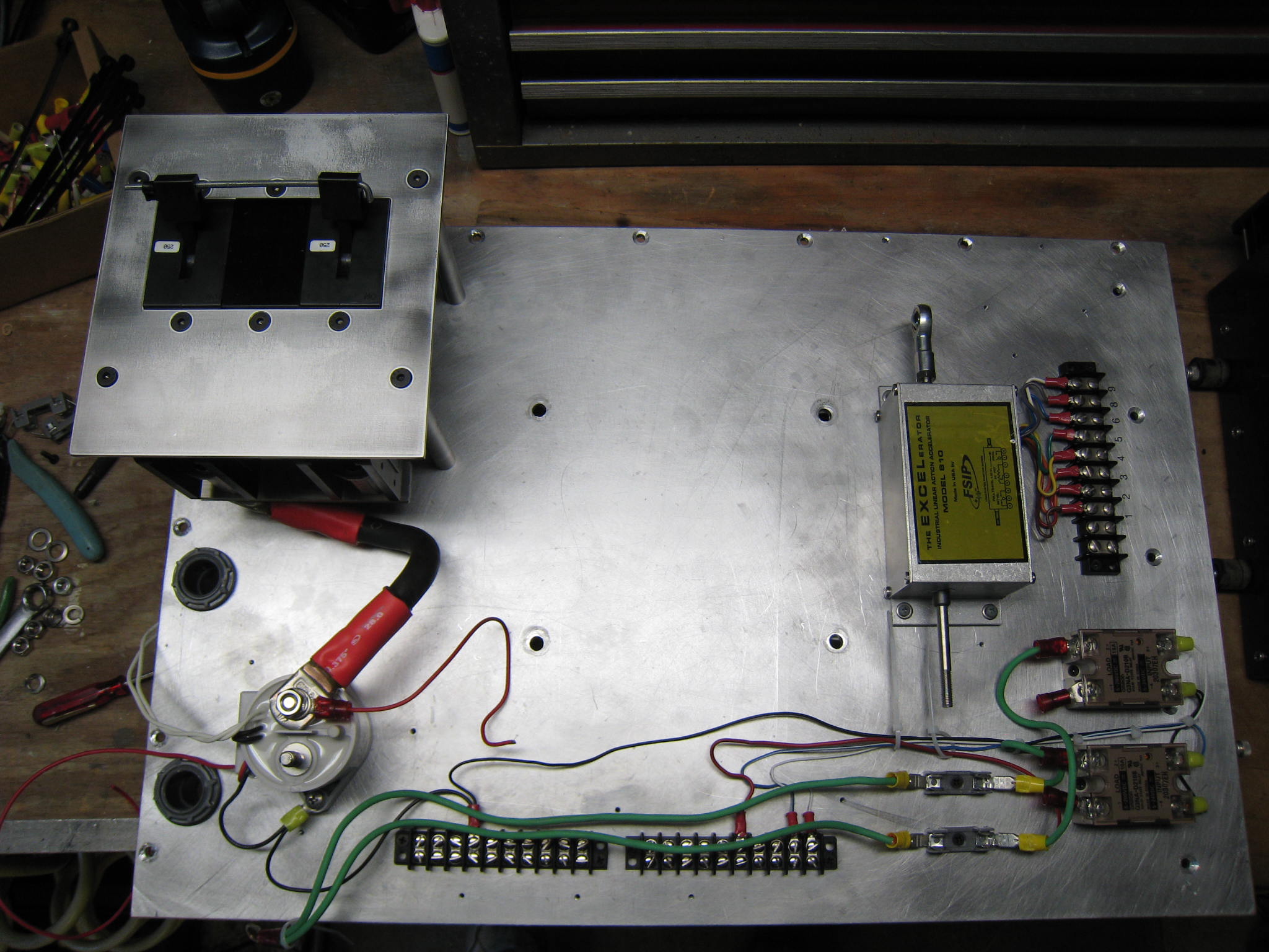 HV base plate with contactor, circuit breaker, and pot box |
||||
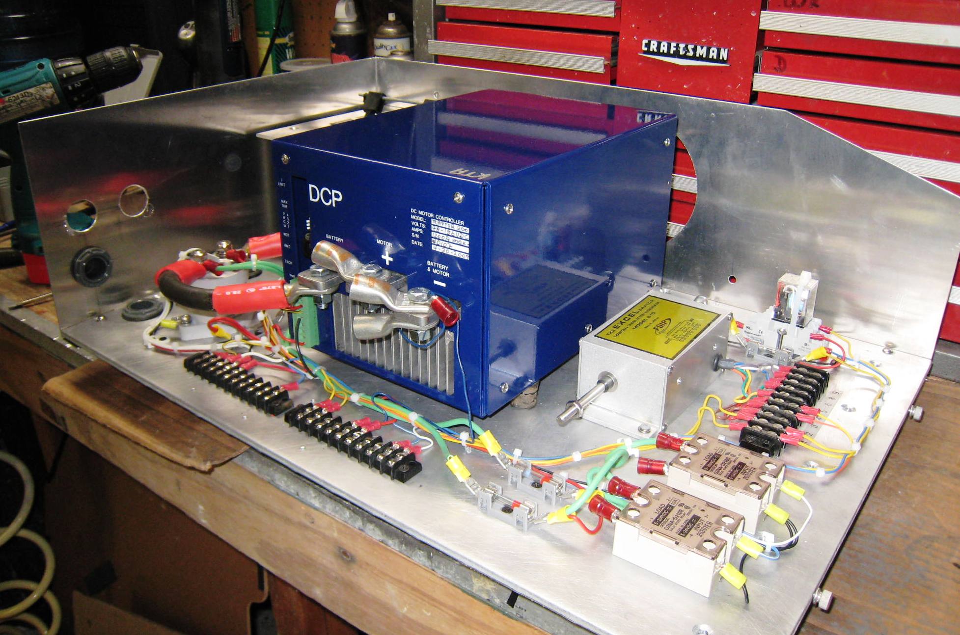 HV assembly base plate, with fixed side and rear wall in place |
 HV assembly fully pre-wired |
||||
| As shown above, the HV assembly is nearly fully assembled and pre-wired. Next it can be moved from the bench to the motor compartment for mounting. | |||||
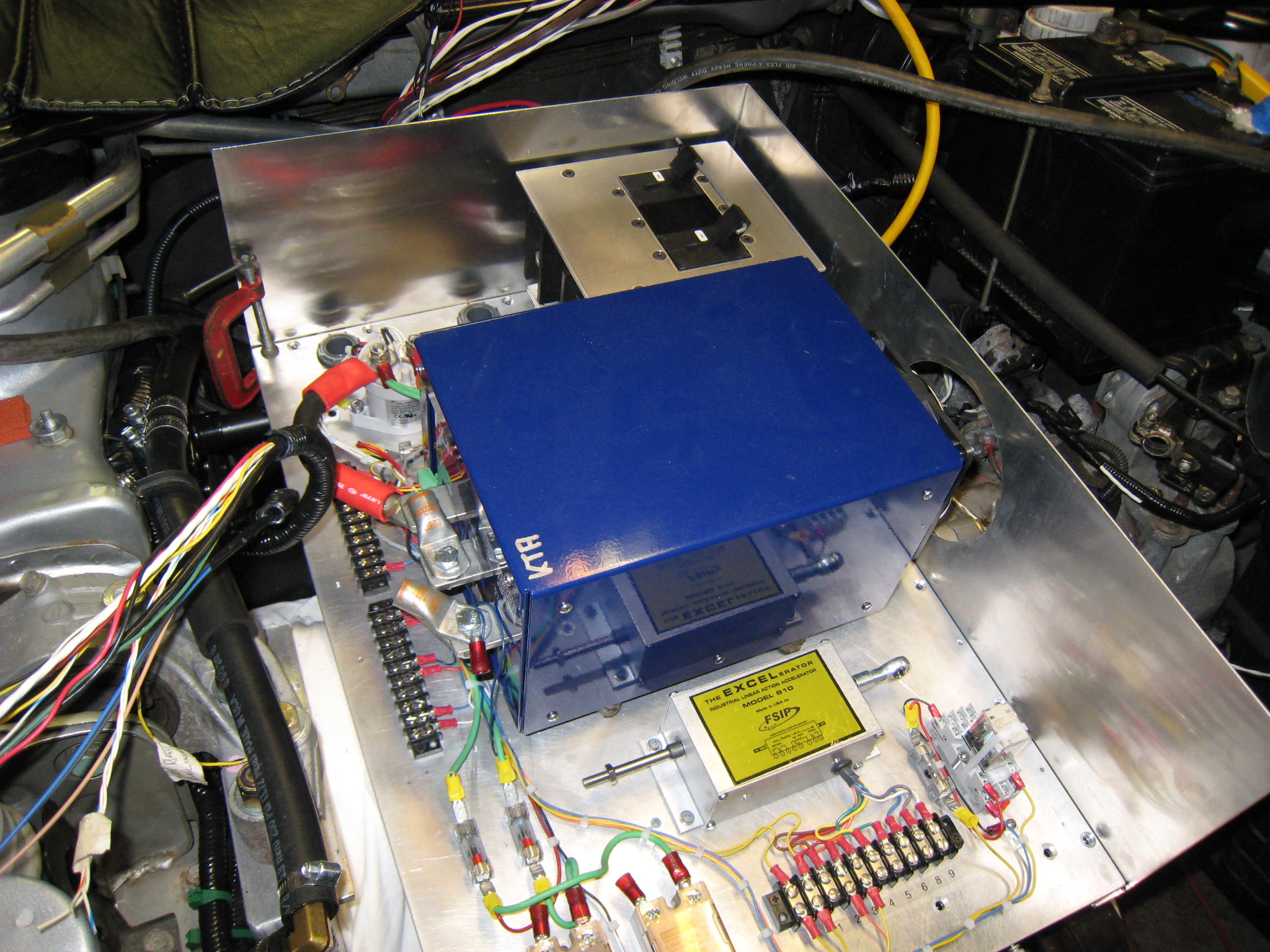
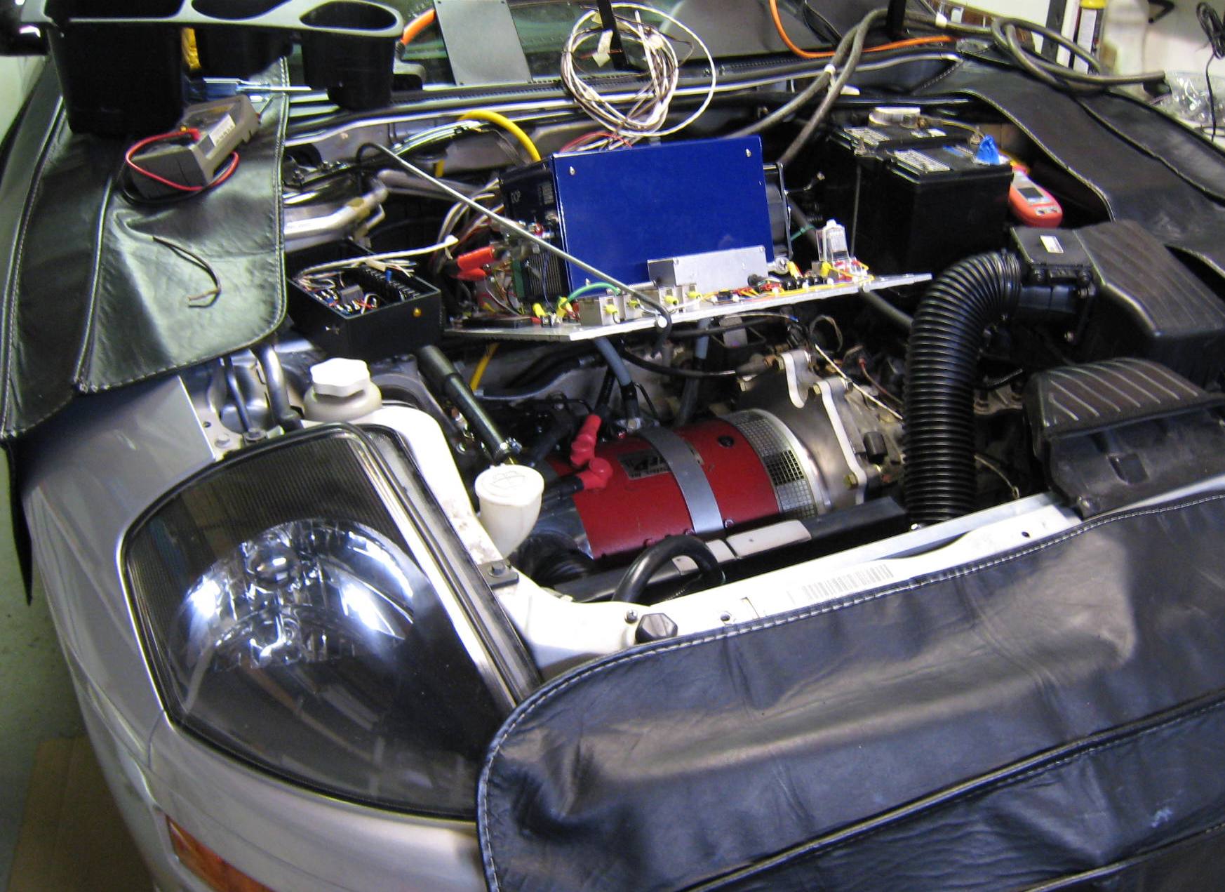
| Regarding the
mounting of the HV assembly, recall an objective was for the assembly/plate
to be lift-able. Accordingly, if you look closely at the upper portion of the image to the right, you will see a black tube, about 1" in diameter, running parallel to and behind the motor. This will be the rear support for the HV assembly, and will enable the plate/assembly to be lifted (at the front) to provide every good access below the assembly, and to the motor. |
 |
||||
 |
Yet a better view of the tubular
rear mounting support, which as shown will enable the tube to rotate when
lifting the front end of the plate. Note also the continued progress of the motor compartment under hood re-harnessing. The triple wrapping approach is clearly shown, with an inner wrap of electrical tape, followed by an application of a plastic corrugated sheathing, followed by another (outer) layer of heavy duty electrical tape. That should be water tight! |
||||
 |
 |
||||
| Initial mounting within the motor compartment | HV Assembly shown in the lifted position | ||||
 |
 |
||||
| View under lifted HV assembly plate | HV Assembly installed and wired | ||||
 |
 |
||||
| Manual disconnect cable installed on circuit breakers | Accel. cable (lower left) & Emergency Cutoff (upper right) | ||||
 The front of the car is essentially ready for initial road testing... It is close to 'smoke test' time! |
|||||
| 12 The Tachometer Saga | |
|
If the donor car has a factory in-dash tachometer, it is actually not that difficult to get the tachometer (tach) working. One simply must locate the engine speed signal cable, which was very easy to locate and re-harness in ED-E, and provide a pulse waveform that is proportional to the motor speed. |
|
| However, with ED-E, this turned out to be quite a saga! The first issue turned out to be the fact that somewhere along the way, a fully working tach before the conversion, was DOA when nearing the end of the major conversion work. It took a while to actually suspect the tach because it was working fine to start with. But at some point I decided to find another dash cluster on the Internet, purchase it, and then verify that the purchased tach unit worked as it was thought to work. Once second tach unit did work as expected, and I applied the same signal to the current/original in-dash tach unit, it was determined that the original as not working. |
 |
Next, the new tach unit was installed in the dash and verified using a function generator by producing and feeding a pulse waveform signal into the engine speed cable that was re-wired and routed to the power steering controller box. The power steering controller box will therefore also function as a junction box. Now attention can be turned the next chore... finding a suitable electronic pickup to sense the motor RPM. This RPM signal must produce two (2) pulses with an amplitude of 0-12 volts, for each revolution of the motor. The reason that there are just two pulses required, instead of the three that would be expected with a tach from a 6-cylinder engine, is that the replacement tach that was purchased, when tested, was determined to have come from a 4-cylinder Eclipse (wherein only two cylinders fire per revolution). See the schematic below from the Eclipse service manual for a clear indication of the engine speed signal, which is a shielded cable.
------------------------------------------------------------------------------------------------------------- There are several sensors made to bolt onto the motor on
the tail shaft side, but with ED-E that was not possible due to the use of
the AC drive pulley. After some research on the Internet, a magnetic reed-switch manufactured by Cherry
was used (click
here for more information). The cherry MP201701was installed along with
some stud magnets, and seemed to work well when manually turning the
shaft of the motor. But when the WarP11 motor was energized, even with
a small 10 to 20 amp current, a magnetic field of the motor completely
saturated the magnetic reed-switch, causing it to close and stay closed,
regardless of the position of the stud magnets mounted to the tail shaft
AC pulley. To explain this a bit differently,
the RPM of the motor was originally to be sensed by 2 stud magnets, which
are threaded into the AC drive pulley. As such, as each magnet passed
closely by the magnetic reed pickup - as they rotate with the motor's shaft
-
the magnetic reed switch closes, and then re-opens when a respective magnet has
passed by. The tach unit simply counts these pulses (2 per revolution)
and displays the engine/motor RPM. But alas, this failed due to the
strong magnetic fields generated by the very large electric motor.
Several magnetic shielding attempts were tried and failed, and so did several
other sensors. |
|
|
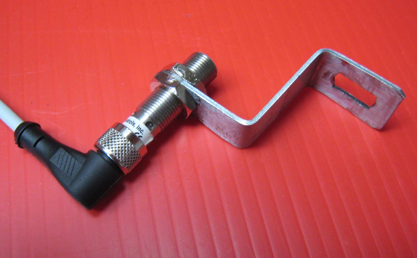
But then I found came across a company named Fargo Controls,
which manufactures a 12mm diameter inductive proximity sensor. The actual
part employed was a Fargo
S3054. Shown at the right is the S3054, with a custom mounting bracket that should do nicely.
|
 |
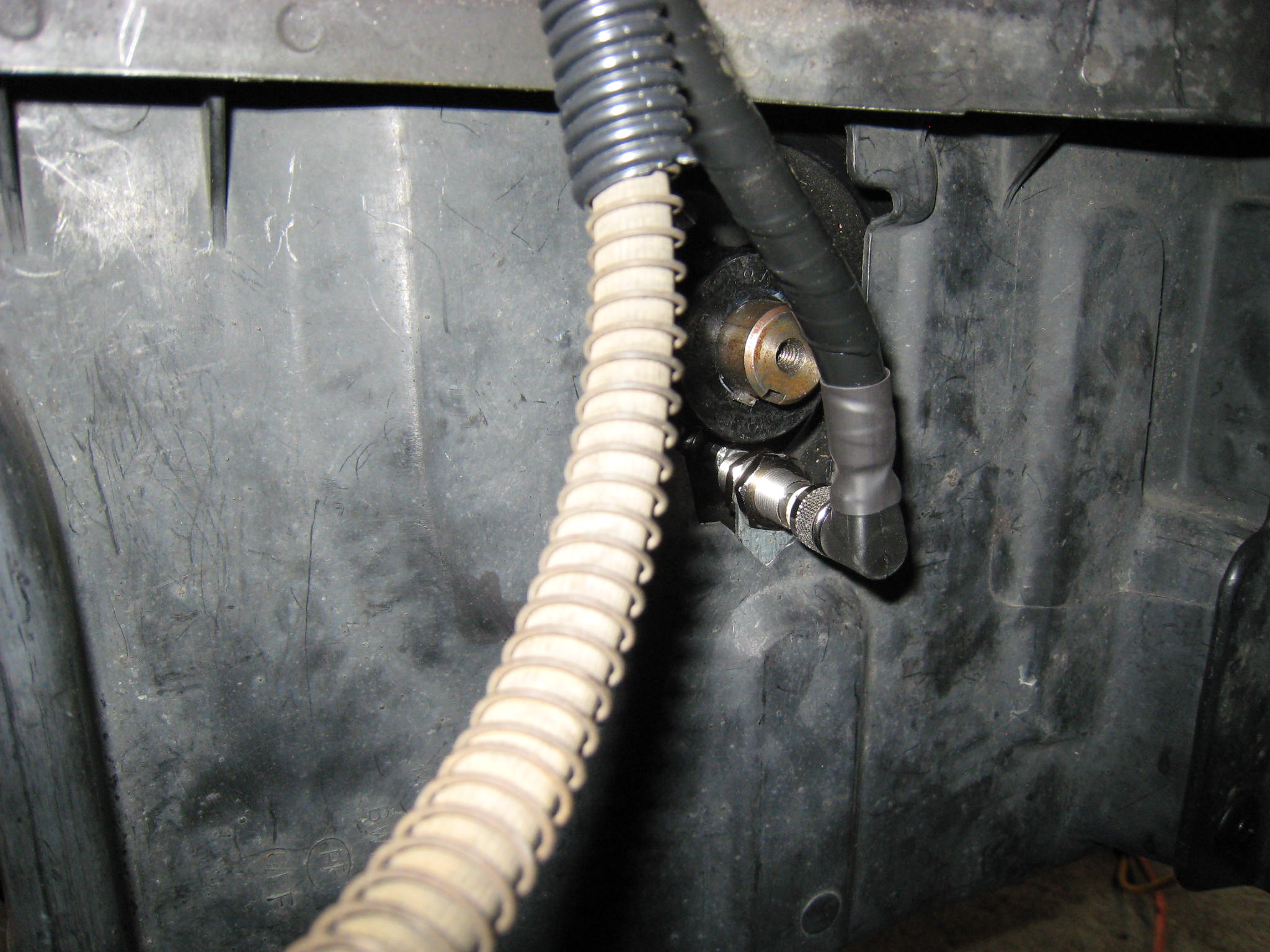 |
Next the wiring harness of the inductive pickup sensor was carefully
wrapped. Shown at the left, the inductive pickup is mounted, and the wrapped harness routed upwardly to the power steering controller (& junction) box.
|
|
|
 |
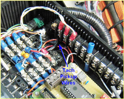 |
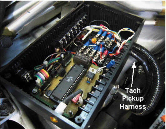
The PS controller box with the S3054 harness wired to a
terminal block and hardwired to the engine speed signal, which is a shielded
cable that runs to the in-dash tach. |
|
A high level schematic for the entire tachometer pickup circuit is provided below... |
|
|
|
|
---------------------------------------------------------------------------------------------------------- |
|
| 13 The Battery Management System (BMS) | |
|
|
|
| * * STILL UNDER
CONSTRUCTION * * * (Check back soon for updates...) |
|
| 14 The Finished Vehicle (Phase-I) | |
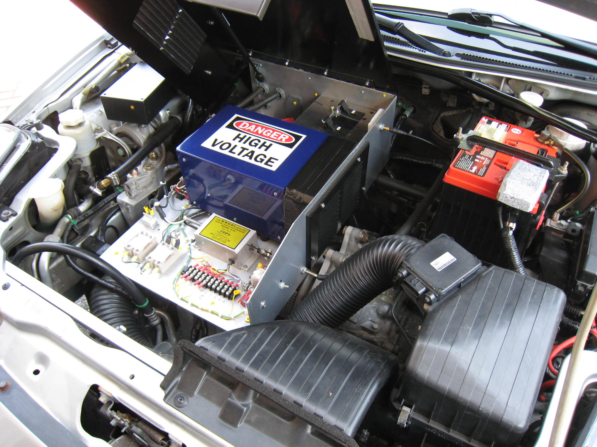
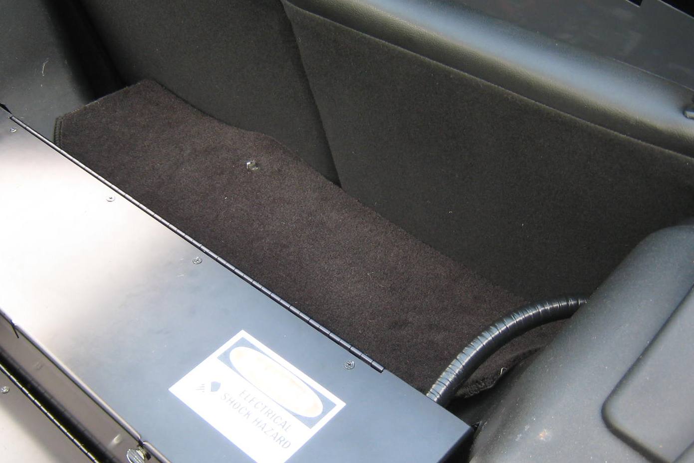
| Under The Hood:. | |
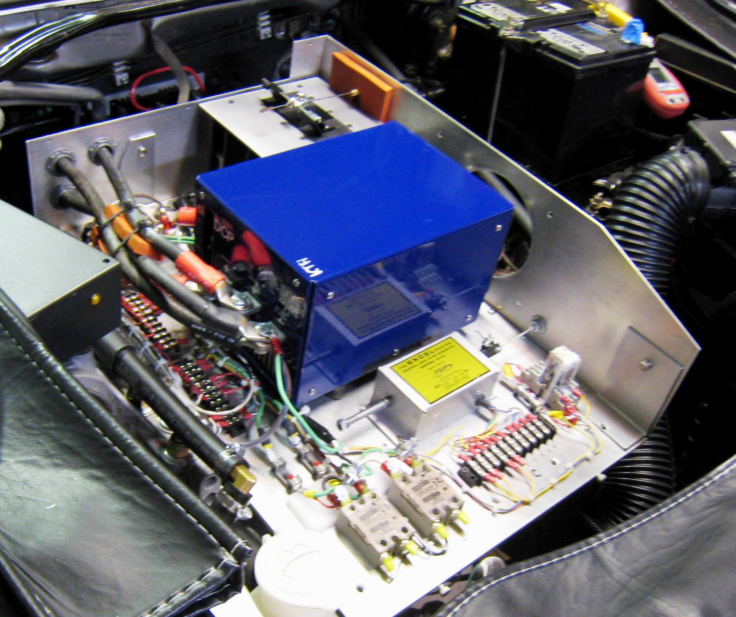
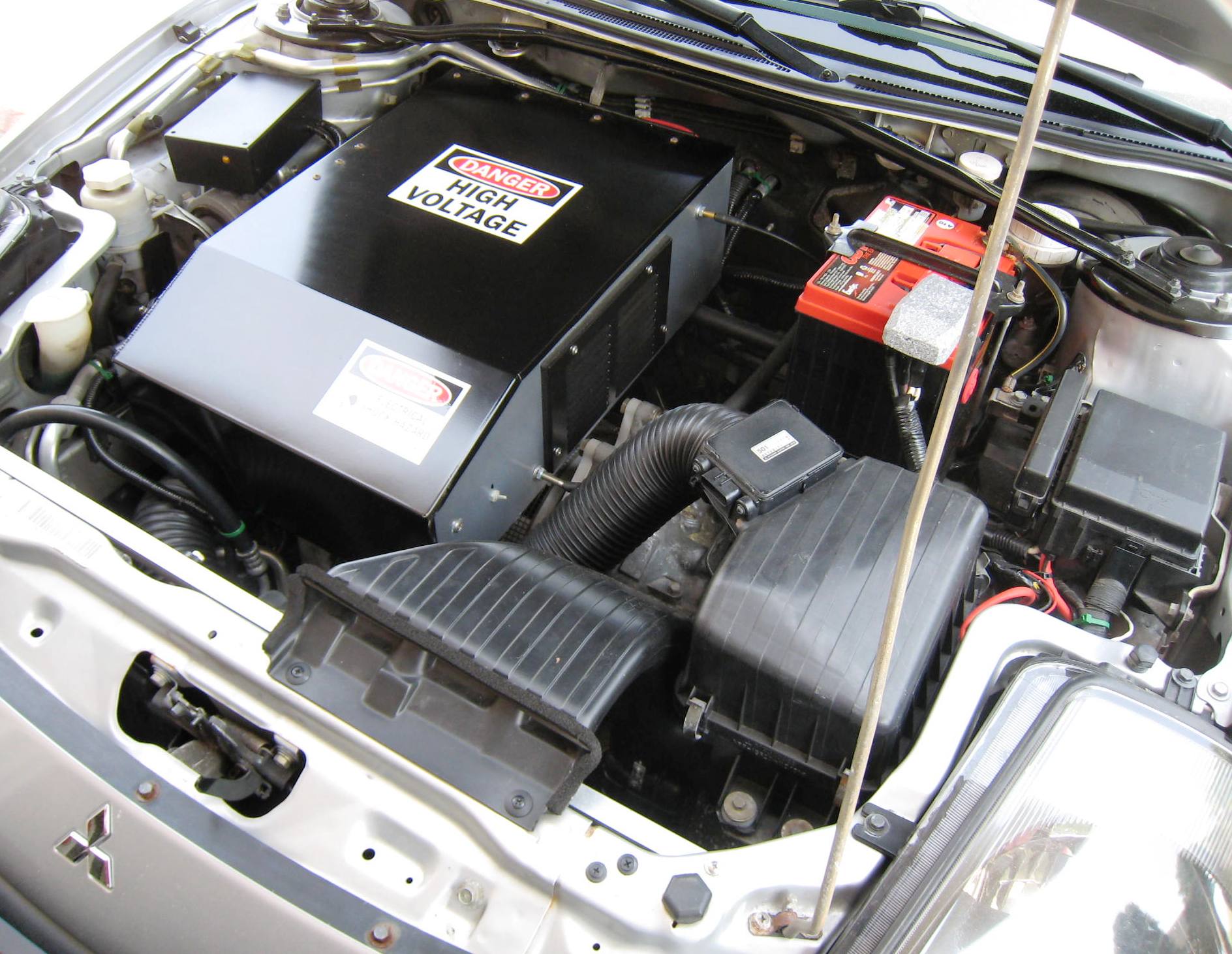 |
 |
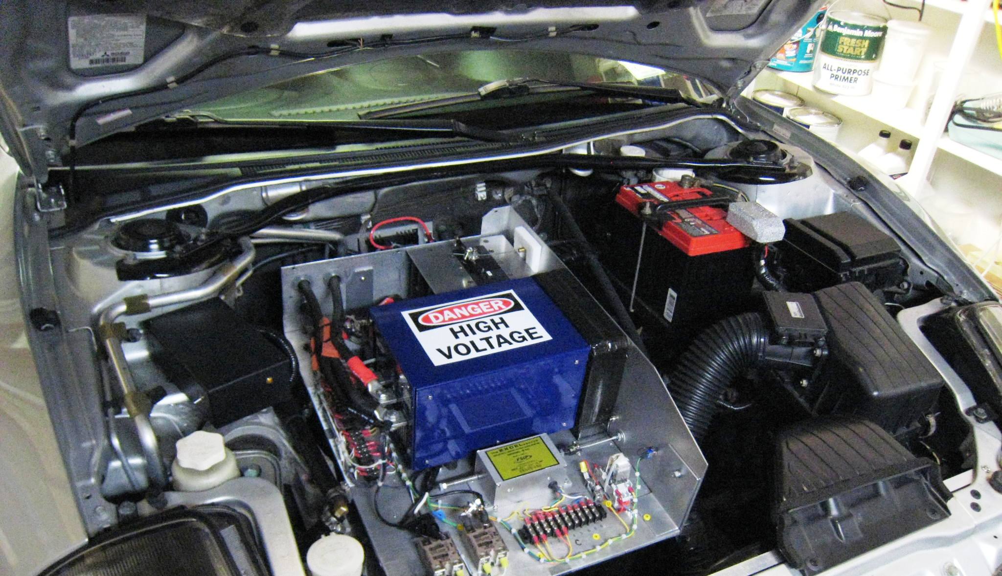
| The finished and covered Front HV Assembly shown from front of car | |
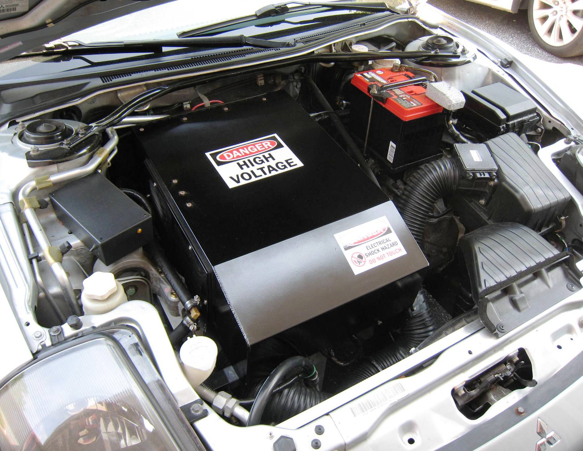
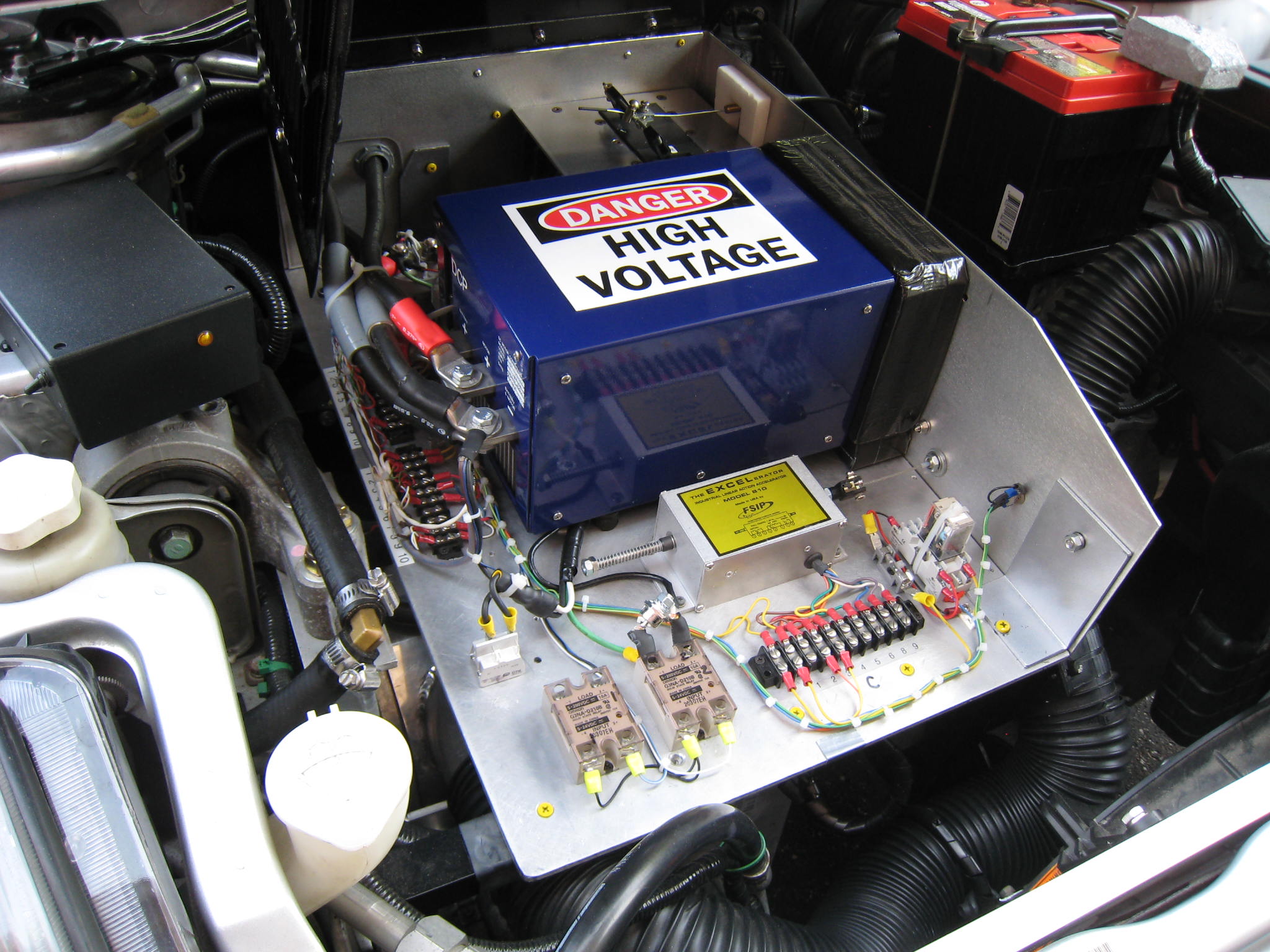
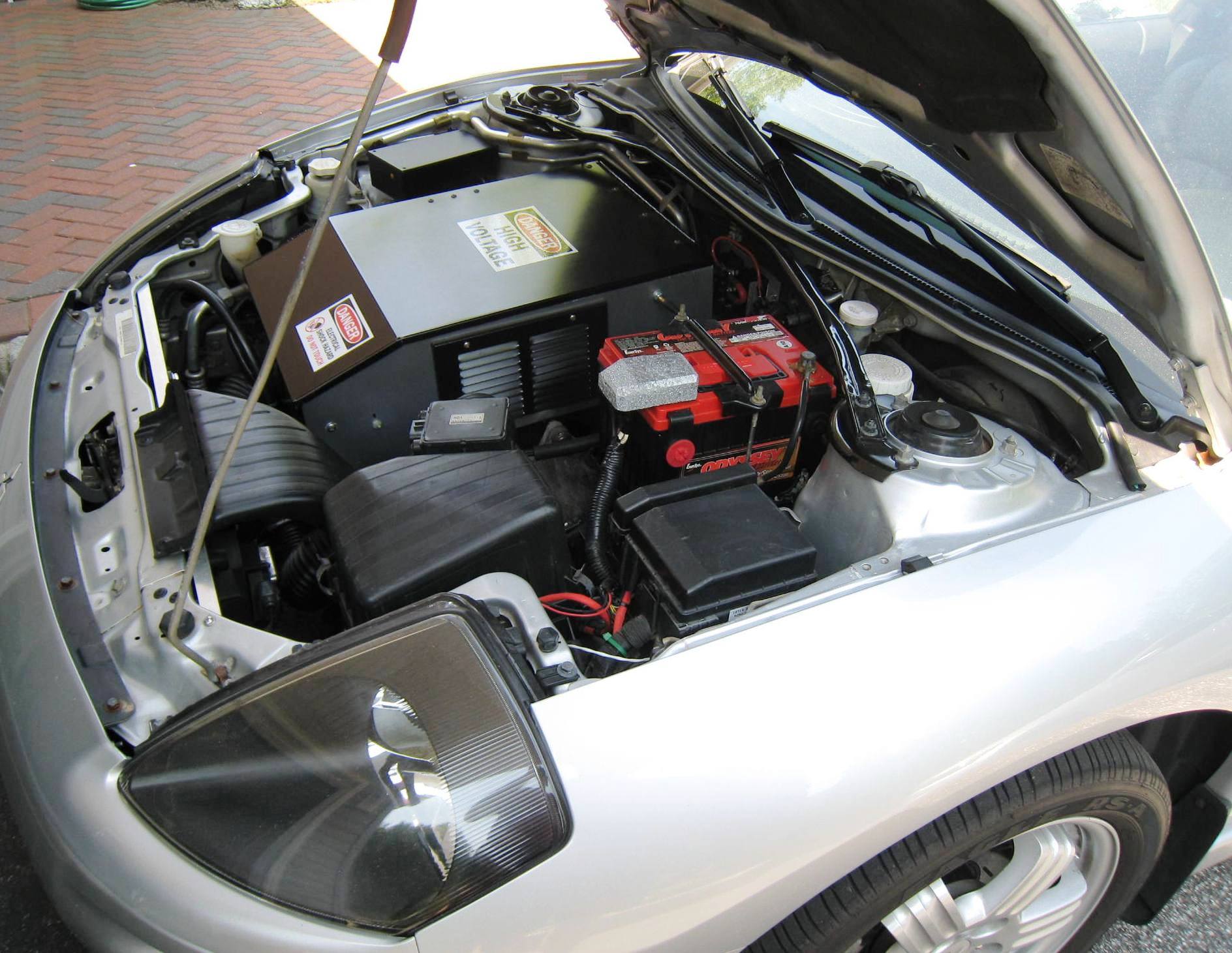 |
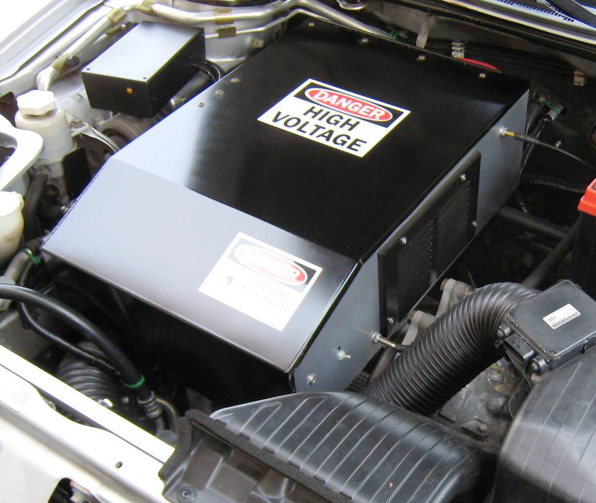 |
| Finished and covered Front HV Assembly shown from side Close-up view of covered Front HV Assembly | |
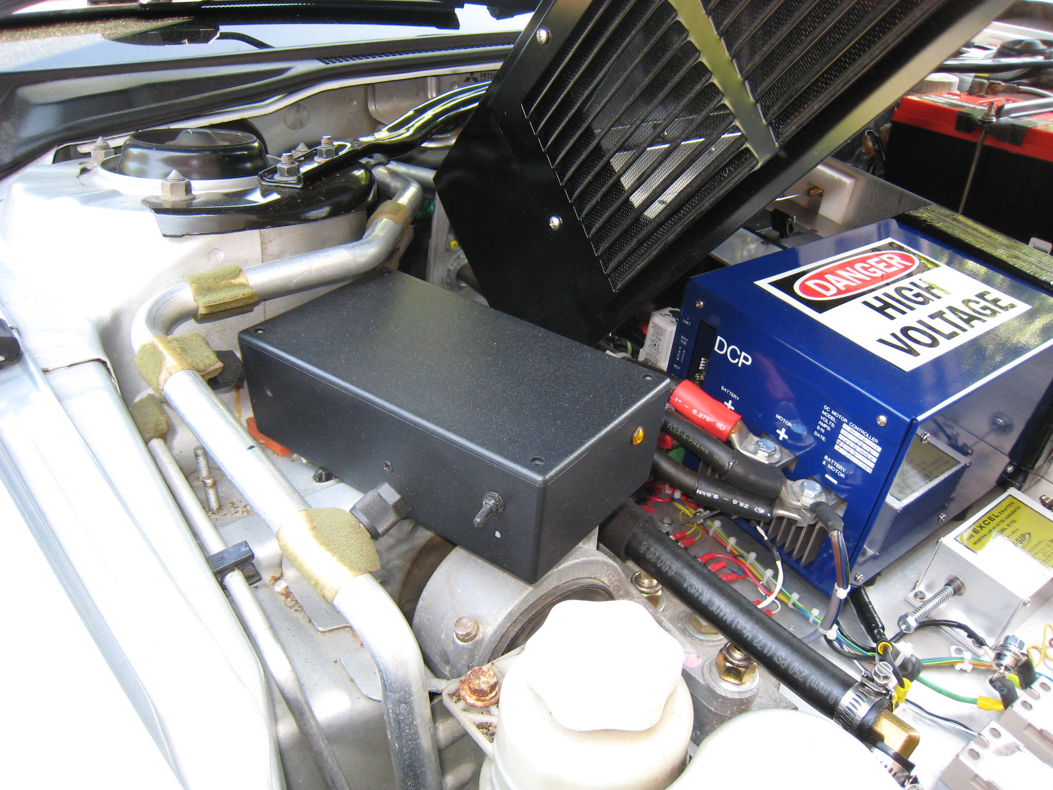
 |
 |
| Front HV Assembly with cover lifted (and supported by included gas shock/strut) | |
 |
 |
|
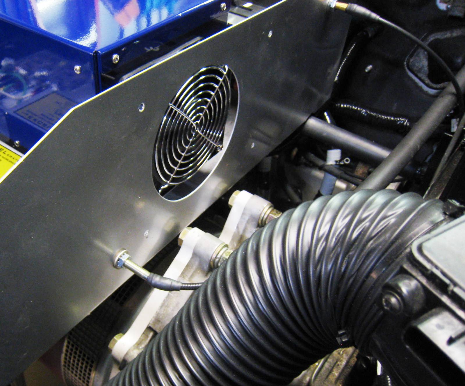
Closeup view showing PS controller box (black), and a tube blower for motor
forced-air cooling
|
|
 |
 |
| AC compressor mounted and belt driven using tail shaft | |
| Mid-Car Bench and Battery Box 1 | |
 |
 |
 |
 |
| Rear High Voltage Contactor Assembly | |
 |
 |
 |
 |
 |
 |
 |
 |
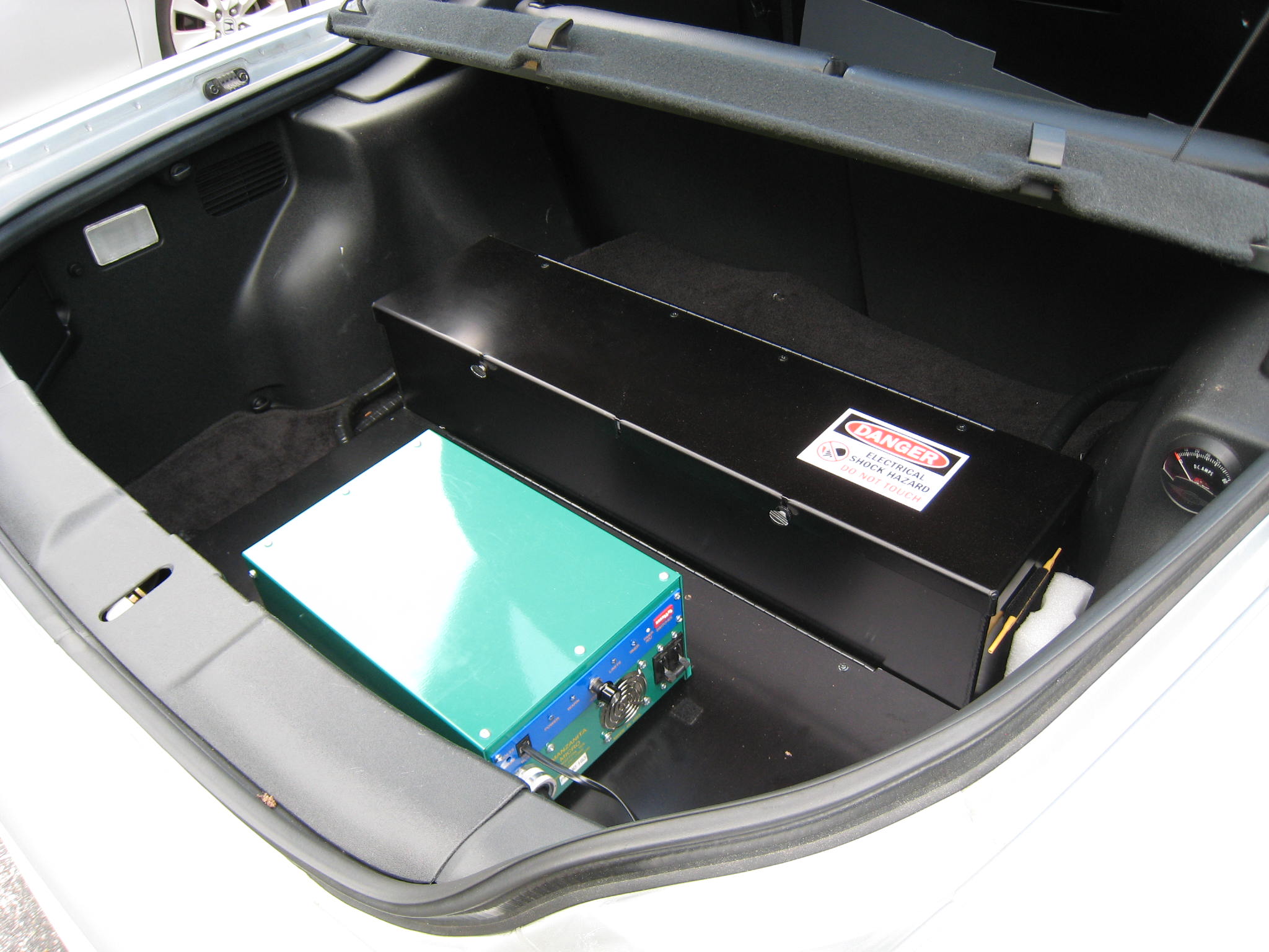
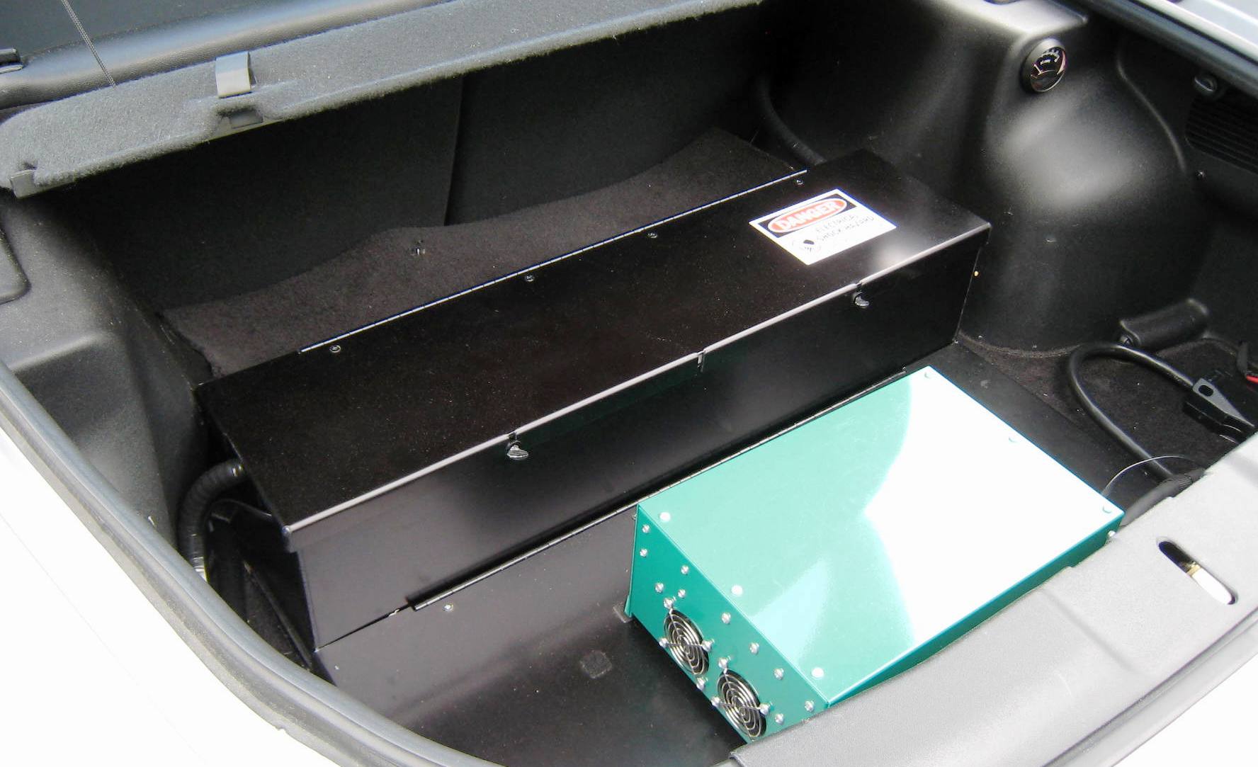
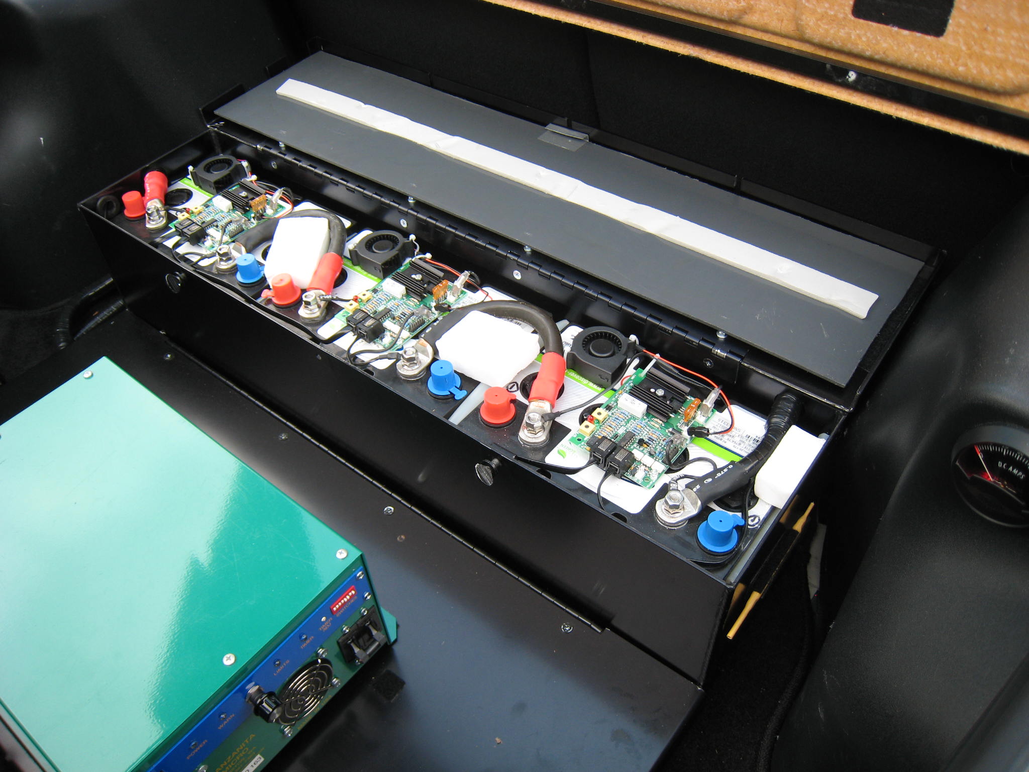
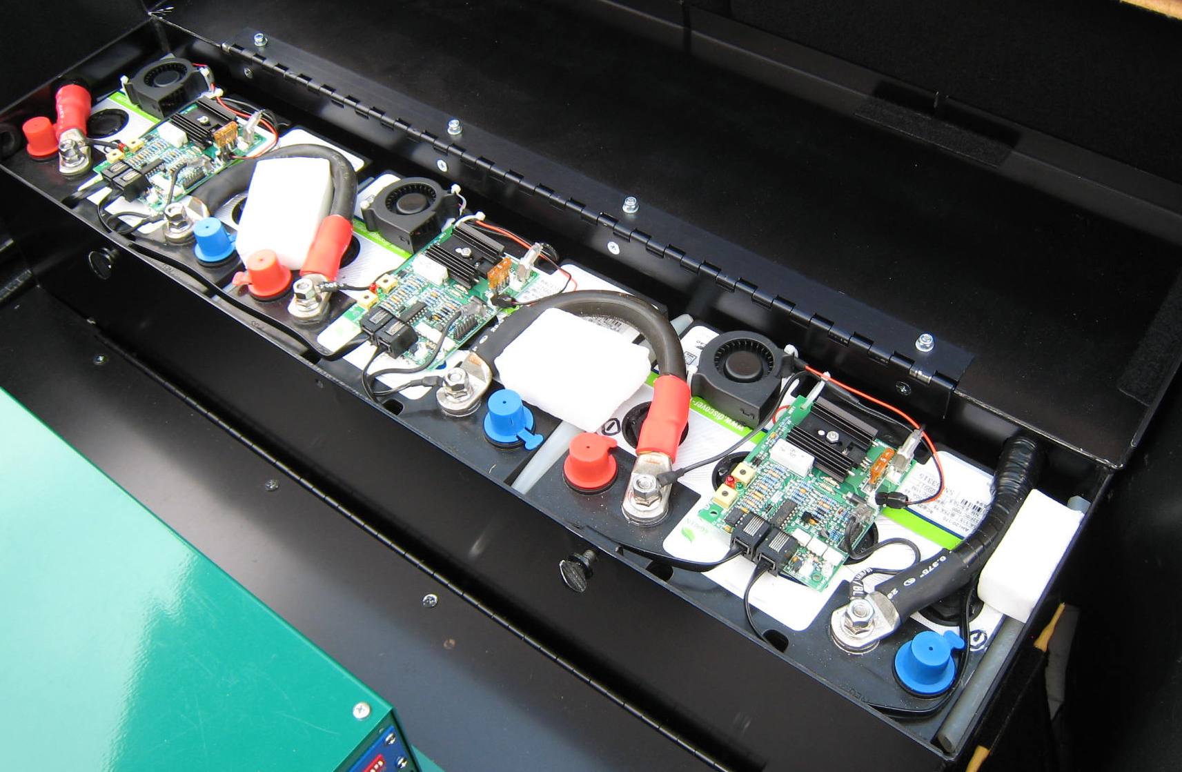
| Trunk, Charger, and Battery Box 2 | |
 |
 |
 |
 |
 |
 |
 |
 |
 |
 |
 |
|
|
|
|
|
|
|
|
|
|